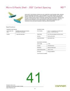
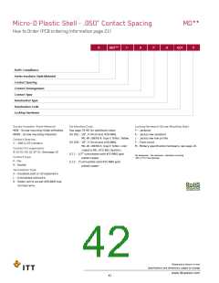
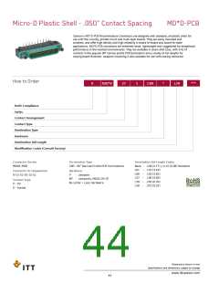
Micro-D Plastic Shell - .050” Contact Spacing
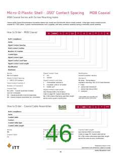
How to Order (PCB ordering information page 21)
MD**
R
MD**
1-
9
P
H
001
P
RoHS Compliance
Series-Insulator Style-Material
Contact Spacing
Contact Arrangement
Contact Type
Termination Type
Termination Code
Locking Hardware
Series-Insulator Style-Material
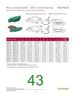
MDB - Screw mounting-Diallyl phthalate
MDVB - Screw mounting-Polyester
Termination Code
See page 79-80 for additional codes
(H) 001 - 18”, 7/34 strand, #26 AWG,
Locking Hardware (Screw Mounting Only)
P - Jackpost
K - Jackscrew-standard
MIL-W-16878/4, Type E Teflon, Yellow.
(H) 003 - 18”, 7/34 strand, #26 AWG,
MIL-W-16878/4, Type E Teflon, color
coded to MIL-STD-681 System I.
(L) 1 - 1/2” uninsulated solid #25 AWG gold
plated copper.
L - Jackscrew-low profile
F - Float mount
M - Military specification hardware, see page 16.
Contact Spacing
1 - .050 (1.27) centers
Contact Arrangements
9-15-21-25-31-37-51. See page 12
No designator - No hardware - standard mounting
.091 (2.31) hole diameter
Contact Type
P - Pin
S - Socket
(L) 2 - 1”uninsulated solid #25 AWG gold
plated copper.
Termination Type
H - Insulated solid or stranded wire
L - Uninsulated solid wire
S - Solder pot to accept #26 AWG max.
harness wire
Dimensions shown in mm
Specifications and dimensions subject to change
www.ittcannon.com
42

 ITT [ ITT Cannon ]