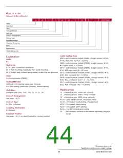
How to order
Cannon Order reference
CA
06
X
H
20
29
S
W
B
–
13-D17-A240
Series
Shell style
Class
Sealing Material
Shell Size
Contact Arrangement
Contact Type
Insulator position
Coupling Mechanism
Dash
Modification
Cable Sealing Area
Cable Sealing Area
D07 = with Universal Endbell (IP69K), straight version: #10SL,
#14S, #20 (wire size 4,5 – 7,2mm)
D09 = with Universal Endbell (IP69K), straight version: #14S,
#20 (wire size 6,5 - 9,3mm)
D11 = with Universal Endbell (IP69K), straight version: #14S,
#18, #20 (wire size 8,0 – 10,3mm)
D13 = with Universal Endbell (IP69K), straight version: #18,
#20, #22 (wire size 9,0 – 12,5mm
D14 = with Universal Endbell (IP69K), straight version: #18,
#20, #22, #28 (wire size 11,5 – 14,2mm)
D17 = with Universal Endbell (IP69K), straight version: #20,
#22, #28 (wire size 14,5 – 16,6mm)
Explanation
Series
CA
Shell style
01 = Cable connection receptacle
02 = Wall mounting receptacle, front panel mounting
06 = Straight plug, without spring washer, friction ring and grommet
Class
X=Environmental (IP69K)
Sealing Material
Without = CR-Sealing (cable seal: Silicone)
H= FKM sealing (cable seal: Silicone), consult factory
Modification
Shell Sizes
13 – shielded version, solder pot contacts
14 – shielded version, metric crimp contacts
15 – shielded version, AWG crimp contacts
A176 – gold plated contact, see pages 54-55
A239 – Zinc Cobalt black plating, VG approved
A232 – Zinc cobalt black plating
Available shell sizes: 10SL, 14S, 18, 20, 22, 28
Contact Arrangement
See pages 13-23
Contact Type
P= Pin, S=Socket
A233 – Zinc cobalt green plating
A240 – Zinc Nickel blue grey plating
Coupling Mechanism
B=Bayonet
F0
– less contacts, contacts to be ordered separately, see page
54-59
Insulator Position
See pages 13-23, no identification for normal position
Dimensions shown in mm
Specifications and dimensions subject to change
44
www.ittcannon.com

 ITT [ ITT Cannon ]