D Subminiature
D*
ɍ
ɍɍ
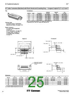
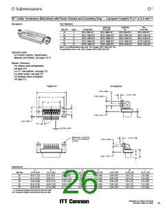
90° Solder Termination (Machined) — European Footprint 10,2 or 9,4 mm
Receptacle
Part Numbers
Shell Size
Layout
9
Through Hole
DE
DA
DB
DC
DD
DE9S-1AON-A197
DA15S-1AON-A197
DB25S-1AON-A197
DC37S-1AON-A197
DD50S-1AON-A197
15
25
37
50
Note: For performance class 2 add -A191. Example: DE9S-1AON-A191-A197
Selection Guide
ɀ For Product Features, Specifications,
Materials and Finishes, see pages 14-15.
Reader’s Resource
ɀ For contact cavity arrangements,
see page 224.
ɀ For P.C. hole patterns, see page 273.
ɀ For panel cutouts, see page 221.
ɀ For hardware views (European),
see page 227.
Engaging Face
DD Configuration
2,54 (.100)
A
C
B
4,70 (.185)
5,08 (.200)
Ø 3,05 (.120)
D
E
L
9,40 (.370)
10°
Ø 0,60 (.024)
4,70 (.185)
2,54 (.100)
9,40 (.370)
F
W
Dimensions
A
B
C
D
E
F
W
L
Shell Size
DE
0,38 (.015)
0,13 (.005)
0,13 (.005)
0,13 (.005)
0,38 (.015)
0,25 (.010)
0,38 (.015)
0,25 (.010)
0,76 (.030)
0,76 (.030)
0,76 (.030)
0,76 (.030)
0,76 (.030)
30,81 (1.213)
39,14 (1.541)
53,04 (2.088)
69,32 (2.729)
66,93 (2.635)
16,33 (.643)
24,66 (.971)
38,38 (1.511)
54,84 (2.159)
52,42 (2.064)
24,99 (.984)
33,32 (1.312)
47,04 (1.852)
63,50 (2.500)
61,11 (2.406)
7,90 (.311)
7,90 (.311)
7,90 (.311)
7,90 (.311)
10,74 (.423)
12,55 (.494)
12,55 (.494)
12,55 (.494)
12,55 (.494)
15,37 (.605)
10,90 (.429)
10,90 (.429)
10,90 (.429)
10,90 (.429)
10,90 (.429)
6,94 (.273)
6,94 (.273)
6,94 (.273)
6,94 (.273)
6,94 (.273)
DA
DB
DC
DD
ɍ Connector footprint measured from the front shell.
ɍɍ Connector footprint measured from the rear shell.
Dimensions are shown in mm (inch)
Dimensions subject to change
21

 ITT [ ITT Cannon ]