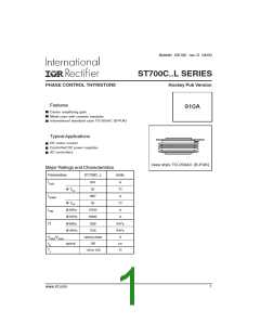
ST700C..L Series
Bulletin I25190 rev. D 04/00
Thermal and Mechanical Specification
Parameter
ST700C..L
Units Conditions
TJ
T
Max. operating temperature range
Max. storage temperature range
-40 to 125
-40 to 150
°C
stg
RthJ-hs Max. thermal resistance,
junction to heatsink
0.073
0.031
DC operation single side cooled
K/W
K/W
DC operation double side cooled
RthC-hs Max. thermal resistance,
case to heatsink
0.011
0.006
14700
(1500)
255
DC operation single side cooled
DC operation double side cooled
F
Mounting force, 10%
N
(Kg)
g
wt
Approximate weight
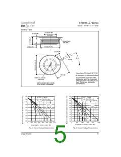
Case style
TO - 200AC (B-PUK)
See Outline Table
∆RthJ-hs Conduction
(The following table shows the increment of thermal resistence RthJ-hs when devices operate at different conduction angles than DC)
Sinusoidal conduction Rectangular conduction
Conduction angle
Units
K/W
Conditions
TJ = TJ max.
Single Side Double Side Single Side Double Side
180°
120°
90°
0.009
0.011
0.014
0.020
0.036
0.009
0.011
0.014
0.020
0.036
0.006
0.011
0.015
0.021
0.036
0.006
0.011
0.015
0.021
0.036
60°
30°
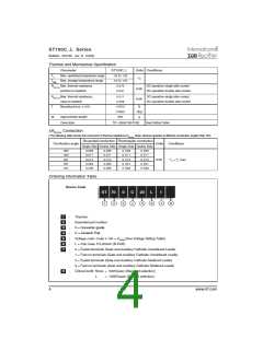
Ordering Information Table
Device Code
ST 70
0
C
20
L
1
1
2
5
6
7
8
3
4
1
2
3
4
5
6
7
-
-
-
-
-
-
-
Thyristor
Essential part number
0 = Converter grade
C = Ceramic Puk
Voltage code: Code x 100 = VRRM (See Voltage Rating Table)
L = Puk Case TO-200AC (B-PUK)
0 = Eyelet terminals (Gate and Auxiliary Cathode Unsoldered Leads)
1 = Fast-on terminals (Gate and Auxiliary Cathode Unsoldered Leads)
2 = Eyelet terminals (Gate and Auxiliary Cathode Soldered Leads)
3 = Fast-on terminals (Gate and Auxiliary Cathode Soldered Leads)
Critical dv/dt: None = 500V/µsec (Standard selection)
8
-
L
= 1000V/µsec (Special selection)
4
www.irf.com

 INFINEON [ Infineon ]