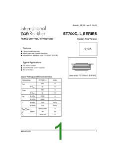
ST700C..L Series
Bulletin I25190 rev. D 04/00
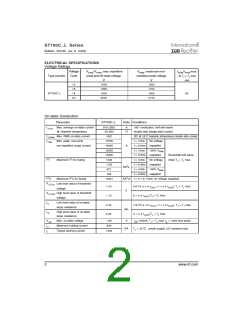
ELECTRICAL SPECIFICATIONS
Voltage Ratings
Voltage
Code
VDRM/VRRM, max. repetitive
VRSM , maximum non-
IDRM/IRRMmax.
@ TJ = TJ max
mA
Typenumber
peak and off-state voltage
repetitive peak voltage
V
V
12
16
18
20
1200
1600
1800
2000
1300
1700
1900
2100
ST700C..L
80
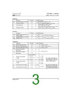
On-state Conduction
Parameter
ST700C..L
Units Conditions
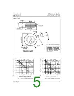
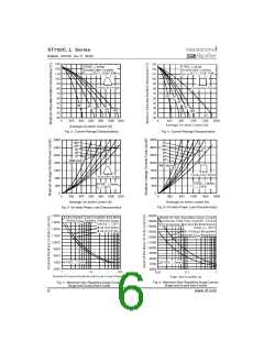
IT(AV) Max. average on-state current
@ Heatsink temperature
910 (355)
55 (85)
1857
A
180° conduction, half sine wave
°C
double side (single side) cooled
IT(RMS) Max. RMS on-state current
DC @ 25°C heatsink temperature double side cooled
t = 10ms No voltage
t = 8.3ms reapplied
t = 10ms 100% VRRM
t = 8.3ms reapplied
t = 10ms No voltage
t = 8.3ms reapplied
t = 10ms 100% VRRM
t = 8.3ms reapplied
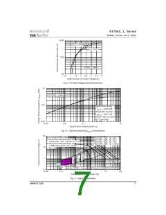
ITSM
Max. peak, one-cycle
15700
16400
13200
13800
1232
1125
871
non-repetitive surge current
A
Sinusoidal half wave,
Initial TJ = TJ max.
I2t
Maximum I2t for fusing
KA2s
795
I2√t
Maximum I2√t for fusing
12321
KA2√s t = 0.1 to 10ms, no voltage reapplied
VT(TO) Low level value of threshold
1
1.00
1.13
(16.7% x π x IT(AV) < I < π x IT(AV)), TJ = TJ max.
voltage
V
VT(TO) High level value of threshold
2
(I > π x IT(AV)),TJ = TJ max.
voltage
rt1
Low level value of on-state
0.40
0.35
(16.7% x π x IT(AV) < I < π x IT(AV)), TJ = TJ max.
mΩ
slope resistance
rt2
High level value of on-state
slope resistance
(I > π x IT(AV)),TJ = TJ max.
VTM
IH
Max. on-state voltage
1.80
600
V
I = 2000A, TJ = TJ max, t = 10ms sine pulse
pk p
Maximum holding current
Typical latching current
mA
TJ = 25°C, anode supply 12V resistive load
IL
1000
2
www.irf.com

 INFINEON [ Infineon ]