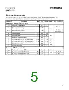
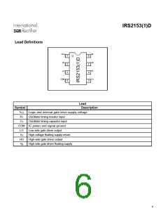
IRS2153(1)D
Bootstrap MOSFET
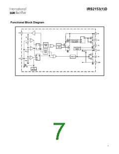
Functional Description
The internal bootstrap FET and supply capacitor (CBOOT) comprise
the supply voltage for the high side driver circuitry. The internal
boostrap FET only turns on when LO is high. To guarantee that
the high-side supply is charged up before the first pulse on pin
HO, the first pulse from the output drivers comes from the LO pin.
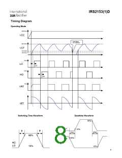
Under-voltage Lock-Out Mode (UVLO)
The under-voltage lockout mode (UVLO) is defined as the state
the IC is in when VCC is below the turn-on threshold of the IC. The
IRS2153(1)D under voltage lock-out is designed to maintain an
ultra low supply current of less than 170 µA, and to guarantee the
IC is fully functional before the high and low side output drivers
are activated. During under voltage lock-out mode, the high and
low-side driver outputs HO and LO are both low.
Normal operating mode
Once the VCCUV+ threshold is passed, the MOSFET M1 opens, RT
increases to approximately VCC (VCC-VRT+) and the external CT
capacitor starts charging. Once the CT voltage reaches VCT
-
Supply voltage
(about 1/3 of VCC), established by an internal resistor ladder, LO
turns on with a delay equivalent to the deadtime (td). Once the CT
voltage reaches VCT+ (approximately 2/3 of VCC), LO goes low, RT
goes down to approximately ground (VRT-), the CT capacitor
discharges and the deadtime circuit is activated. At the end of the
deadtime, HO goes high. Once the CT voltage reaches VCT-, HO
goes low, RT goes high again, the deadtime is activated. At the
end of the deadtime, LO goes high and the cycle starts over
again.
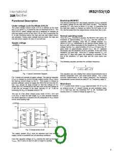
+ AC Rectified Line
RVCC
VCC
RT
VB
HO
VS
LO
1
2
3
4
8
7
6
5
CBOOT
MHS
RT
CT
L
The following equation provides the oscillator frequency:
CVCC
CT
COM
RL
MLS
1
f ~
1.453× RT ×CT
- AC Rectified Line
Fig. 1 Typical Connection Diagram
This equation can vary slightly from actual measurements due to
internal comparator over- and under-shoot delays. For a more
accurate determination of the output frequency, the frequency
characteristic curves should be used (RT vs. Frequency, page 3).
Fig. 1 shows an example of supply voltage. The start-up capacitor
(CVCC) is charged by current through supply resistor (RVCC) minus
the start-up current drawn by the IC. This resistor is chosen to
provide sufficient current to supply the IRS2153(1)D from the DC
bus. CVCC should be large enough to hold the voltage at Vcc
above the UVLO threshold for one half cycle of the line voltage as
it will only be charged at the peak, typically 0.1 uF. It will be
necessary for RVCC to dissipate around 1 W.
Shut-down
If CT is pulled down below
(approximately 1/6 of VCC) by
V
CTSD
an external circuit, CT doesn’t charge up and oscillation stops.
LO is held low and the bootstrap FET is off. Oscillation will
resume once CT is able to charge up again to VCT-
.
The use of a two diode charge pump made of DC1, DC2 and
CVS (Fig. 2) from the half bridge (VS) is also possible however
the above approach is simplest and the dissipation in RVCC should
not be unacceptably high.
+ AC Rectified Line
RVCC
VCC
RT
VB
HO
VS
LO
1
2
3
4
8
7
6
5
CBOOT
MHS
DC2
RT
CT
L
CVCC
CVS
CT
COM
RL
MLS
DC1
- AC Rectified Line
Fig. 2 Charge pump circuit
The supply resistor (RVCC) must be selected such that enough
supply current is available over all operating conditions.
Once the capacitor voltage on VCC reaches the start-up threshold
VCCUV+, the IC turns on and HO and LO begin to oscillate.
9

 INFINEON [ Infineon ]