PWM Doubler/Quad Logic
IR3599/IR3599A
IR ACTIVE TRI-LEVEL (ATL) PWM
INPUT/OUTPUT SIGNAL
GENERAL DESCRIPTION
IR3599/IR3599A is a phase multiplier which is
designed for high phase count applications to reduce
the number of interface signals between controller and
drivers. Each IR3599/IR3599A can be configured to
drive up to four independent power stages from one
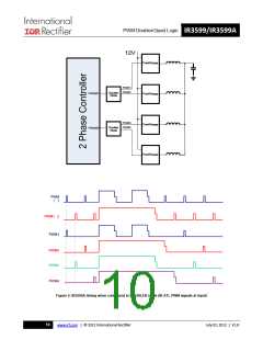
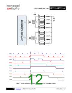
PWM input. When it is configured in doubler mode,
only two PWM output signals are controlled by the
single PWM input. The doubler logic alternates the
two PWM outputs at half of the PWM input frequency
so that it can generate two out of phase PWM signals.
The rest two PWM output are in tri-state. When it is
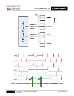
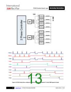
configured in quad mode, all four PWM output are
controlled by the single PWM input. The quad logic
will alternate the four PWM outputs at 0º, 90º, 180º,
and 270º respectively, and each at 1/4 of the PWM
input frequency. The phase modes for doubler and
quad are shown in Figure 4.
The IR3599A is driven by a patented active tri-level
(ATL) PWM control signal provided by the IR digital
PWM controllers and also delivers the ATL PWM
signals to the following power stages. During normal
operation, PWM input signal swings between 0V and
1.8V and the generated PWM output signals also
swings between 0 and 1.8V. When PWM input signal
crosses a voltage level higher than the Tri-level high
threshold, it will enter tri-state operation. The IR3599A
provides a 1.0mA typical pull-up current to drive the
PWM input to the tri-state condition of 3.3V when the
PWM controller output is in its high impedance state.
The 1.0mA typical current is designed for driving worst
case stray capacitances and transition the IR3599A
into the tri-state condition rapidly to avoid a prolonged
period of conduction in the following power stage
during faults. This fast tri-state operation eliminates
the need for any tri-state hold-off time of the PWM
signal to dwell in the shutdown window. Immediately
after the IR3599A is driven into the tri-state mode, the
1mA current is disabled so that power is conserved.
Once the IR3599A enters tri-state operation, all of the
PWM outputs will be transitioned to high impedance
states in order to also transition the power stages into
tri-state. This allows the system to operate in single
phase mode when PS2 mode is the mode mode of
operation.
IR3599A features the patented IR Active Tri-Level
(ATL) PWM input and output, designed to work with
IR digital multi-phase controller and IR PowIRstage.
IR3599 features industry’s standard tri-state PWM
input and output interfaces, designed to work with
general multi-phase controllers, drivers or power
stages.
THEORY OF OPERATION
When the PWM input signal level falls below the
tri-level low threshold, the IR3599A will switch back
into normal operation.
POWER-ON RESET (POR)
IR3599/IR3599A incorporates a power-on reset
feature, which ensures the device is active only after
the supply voltage is high enough to generate 1.8V.
INDUSTRY STANDARD TRI-STATE PWM
INPUT/OUTPUT SIGNAL
The IR3599 accepts industry’s standard 3.3V and 5V
tri-state PWM signals. It doubles or quadruples the
single PWM input and then delivers multi-phase PWM
signals to the drivers or power stages. During normal
operation, the PWM input swings from ground to 3.3V
or 5V and the generated PWM output signals will
swing from ground to VCC. If the PWM input is
released from the controller side or if the PWM level is
within a range of 1.65V, the IR3599 will enter tri-state
operation. The floating PWM input will be driven by
the IR3599 to its tri-state window and all the PWM
outputs will also transition to tri-state.
IR3599/IR3599A is powered from 3.3V DC supply.
An internal LDO generates a 1.8V rail to power the
PWM output in IR3599A. During initial startup,
the 1.8V rail follows the rising 3.3V supply voltage,
proportional to an internal resistor tree. All PWM
outputs are disabled and in a high impedance state
before the VCC supply voltage exceeds the POR
rising threshold.
During normal operation the IR3599/IR3599A
continue to remain active until the VCC supply voltage
falls below the POR falling threshold.
14
www.irf.com | © 2012 International Rectifier
July 02, 2012 | V1.8

 INFINEON [ Infineon ]