IR2166
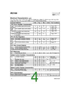
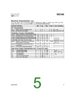
Electrical Characteristics cont.
V
CC
V
= V = V
= 14V +/- 0.25V, V
= Open, R = 39.0kΩ, R = 100kΩ C = 470 pF, V
= 0.0V, V = 0.0V,
CPH SD
BS
BIAS
BUS
T
PH
,
T
= 0.0V V = 0.0V, C
C
= 1000pF, T = 25oC unless otherwise specified.
LO = HO
A
COMP
CS
Symbol Definition
RT Characteristics
Min. Typ.
Max. Units Test Conditions
µA
I
Open circuit RT pin leakage current
—
—
0.1
0
—
—
CT = 10V
RTLK
> or CS >
SD 5.0V 1.3V
V
Fault-mode pin voltage
mV
RTFLT
RT
Protection Circuitry Characteristics
V
Rising shutdown pin reset threshold voltage 4.5
5.2
150
3.0
1.0
1.2
75
5.6
350
3.6
1.6
1.3
90
V
SDTH+
V
V
V
Shutdown pin 5.0V threshold hysteresis
Rising shutdown pin end-of-life threshold volt.
100
2.4
mV
SDHYS
SDEOL+
V
>12V
CPH
-
Falling shutdown pin end-of-life threshold volt. 0.7
V
SDEOL
V
Over-current sense threshold voltage
0.91
25
V
>7.5V
CPH
CSTH+
-
Cycles
V
>7.5V, CYCLES
CPH
Number of sequential over-current fault
cycles before IC shuts down
#FAULT
CS > 1.3V
V
V
BUSUV- The VBUS threshold below which the IC
shuts down
2.6
3.0
12
3.3
V
CPH
CPH pin end-of-life enable threshold
10.3
13.2
Gate Driver Output Characteristics (HO, LO and PFC pins)
VOL
VOH
Low-level output voltage
High-level output voltage
—
—
0
0
100
100
Io = 0
mV
V
- Vo, Io = 0
BIAS
tr
Turn-on rise time
Turn-off fall time
—
—
110
55
300
400
210
160
—
C
= 1nF
= C = C
LO PFC
HO
nsec
mA
tf
—
—
I0+
I0-
HO, LO, PFC source current
HO, LO, PFC sink current
—
www.irf.com
5

 INFINEON [ Infineon ]