IR2166
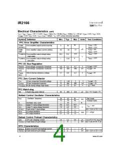
Electrical Characteristics cont.
V
CC
V
= V = V
= 14V +/- 0.25V, V
= Open, R = 39.0kΩ, R = 100kΩ C = 470 pF, V
= 0.0V, V = 0.0V,
CPH SD
BS
BIAS
BUS
T
PH
,
T
= 0.0V, V = 0.0V, C
C
= 1000pF, T = 25oC unless otherwise specified.
LO = HO
A
COMP
CS
Symbol Definition
Min. Typ.
Max. Units Test Conditions
PFC Error Amplifier Characteristics
I
V
V
V
V
V
= 14V
= 3.5V
= 14V
= 4.5V
= 3.0V
55
COMP
Error amplifier output current sourcing
5
35
-30
CPH
BUS
CPH
BUS
BUS
SOURCE
µA
I
-12
14.5
4
COMP
Error amplifier output current sinking
-62
10.5
—
SINK
V
COMPOH Error amplifier output voltage swing
(high state)
13.5
0.25
V
V
V
= 5.0V
COMPOL Error amplifier output voltage swing
(low state)
BUS
PFC DC Bus Regulation
V
V
COMP
= 4.0V
= 4V
BUSOV
Overvoltage comparator threshold
Overvoltage comparator hysterisis
3.8
150
4.3
300
4.7
400
V
mV
V
V
COMP
BUSOV
HYS
V
V
= 4V
VBUS internal reference voltage
3.7
4.0
4.2
V
VBUS
COMP
REG
PFC Zero Current Detector
V
V
V
1.1
75
2
800
9.1
V
= 4V
= 4V
ZX pin comparator threshold voltage
1.65
300
7.5
V
mV
V
ZX
COMP
V
I
ZX pin comparator hysterisis
ZXhys
ZXclamp
COMP
= 5mA
ZX pin clamp voltage (high state)
6.3
ZX
PFC Watch-dog
t
= 0V, V
=2V
WD
Watch-dog pulse interval
90
400
824
µS
ZX
COMP>
Ballast Control Oscillator Characteristics
f
Oscillator frequency
39
73
—
42
78
50
8.4
4.6
0
50
84
—
Run mode
Preheat mode
osc
kHz
%
d
V
Oscillator duty cycle
C
C
6.8
1.8
—
10.7
5.6
—
Upper
Lower
ramp voltage threshold
ramp voltage threshold
CT+
T
V
CC
= 14V
V
V
CT-
T
C
>
or CS >
1.3V
V
t
t
Fault-mode
lead voltage
T
SD 5.0V
CTFLT
DLO
0.7
0.7
1.0
1.0
1.5
1.5
LO output deadtime
HO output deadtime
usec CT = 470pF
DHO
Ballast Control Preheat Characteristics
CPH
V
=5V,CT=0V, V
=0V
I
CPH pin charging current
2.6
—
3.2
0
4.6
—
µA
mV
CPH BUS
> or CS >
SD 5.0V 1.3V
V
Fault-mode pin voltage
CPHFLT
CPH
RPH Characteristics
µA
I
Open circuit RPH pin leakage current
—
—
0.1
0
—
—
RPHLK
>
or CS >
1.3V
V
Fault-mode pin voltage
mV
SD 5.0V
RPHFLT
RPH
4
www.irf.com

 INFINEON [ Infineon ]