IR11682S
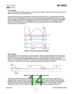
Turn-off phase
Once the SR MOSFET has been turned on, it will remain on until the rectified current will decay to the level
where VDS will cross the turn-off threshold VTH1
.
Since the device currents are sinusoidal here, the device VDS will cross the VTH1 threshold with a relatively
low dV/dt. Once the threshold is crossed, the current will start flowing again through the body diode, causing
the VDS voltage to jump negative. Depending on the amount of residual current, VDS may once again trigger
the turn-on threshold; hence, VTH2 is blanked for a time duration tBLANK after VTH1 is triggered. When the
device VDS crosses the positive reset threshold VTH3, tBLANK is terminated and the IC is ready for next
conduction cycle as shown below.
VTH3
IDS
VDS
T1
T2
VTH1
VTH2
Gate Drive
Blanking
MOT
tBLANK
time
Figure 2: Secondary currents and voltages
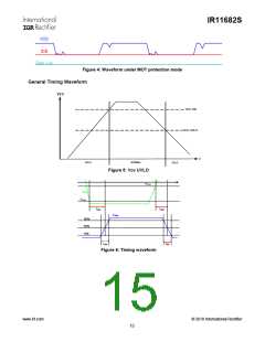
MOT protection
At very light load or no load condition, the current in SR FET will become discontinuous and could be shorter
than MOT time in some system. If this happens, the SR FET current will flow from drain to source at the end
of MOT. The reverse current discharges output capacitor; stores the energy in transformer and causes
resonant on VDS voltage once the SR FET turns off. The resonant could turn on the gate of IR11682, caused
more reverse current and thus subsequent multi false triggering as shown below in Figure 3.
Figure 3: Waveform without MOT protection
The cycle-by-cycle MOT protection circuit can detect the reverse current situation and disable the next
output gate pulse to avoid this issue. The internal comparator and MOT pulse generator still work under the
protection mode. So the circuit can continuously monitor the load current and come back to normal working
mode once the load current conduction time increased to longer than MOT. This circuit helps to reduce
standby power losses. It also can prevent voltage spike that caused by false triggering at light load.
www.irf.com
© 2010 International Rectifier
14

 INFINEON [ Infineon ]