IR11682S
General Description
The IR11682 Dual Smart Rectifier controller IC is the industry first dedicated high-voltage controller IC for
synchronous rectification in resonant converter applications. The IC can emulate the operation of the two
secondary rectifier diodes by correctly driving the synchronous rectifier (SR) MOSFETs in the two secondary
legs.
The core of this device are two high-voltage, high speed comparators which sense the drain to source voltage
of the MOSFETs differentially. The device current is sensed using the RDSON as a shunt resistance and the
GATE pin of the MOSFET is driven accordingly. Dedicated internal logic then manages to turn the power
device on and off in close proximity of the zero current transition.
IR11682 further simplifies synchronous rectifier control by offering the following power management features:
-Wide VCC operating range allows the IC to be directly powered from the converter output
-Shoot through protection logic that prevents both the GATE outputs from the IC to be high at the same time
-Device turn ON and OFF in close proximity of the zero current transition with low turn-on and turn-off
propagation delays; eliminates reactive power flow between the output capacitors and power transformer
-Internally clamped gate driver outputs that significantly reduce gate losses.
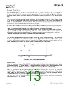
The SmartRectifier™ control technique is based on sensing the voltage across the MOSFET and comparing
it with two negative thresholds to determine the turn on and off transitions for the device. The rectifier current
is sensed by the input comparators using the power MOSFET RDSON as a shunt resistance and its GATE is
driven depending on the level of the sensed voltage vs. the 3 thresholds shown below.
VGate
VDS
VTH2
VTH1
VTH3
Figure 1: Input comparator thresholds
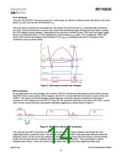
Turn-on phase
When the conduction phase of the SR FET is initiated, current will start flowing through its body diode,
generating a negative VDS voltage across it. The body diode has generally a much higher voltage drop than
the one caused by the MOSFET on resistance and therefore will trigger the turn-on threshold VTH2
.
When VTH2 is triggered, IR11682 will drive the gate of MOSFET on which will in turn cause the conduction
voltage VDS to drop down to ID*RDSON. This drop is usually accompanied by some amount of ringing, that
could trigger the input comparator to turn off; hence, a fixed Minimum On Time (MOT) blanking period is
used that will maintain the power MOSFET on for a minimum amount of time.
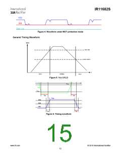
The fixed MOT limits the minimum conduction time of the secondary rectifiers and hence, the maximum
switching frequency of the converter.
www.irf.com
© 2010 International Rectifier
13

 INFINEON [ Infineon ]