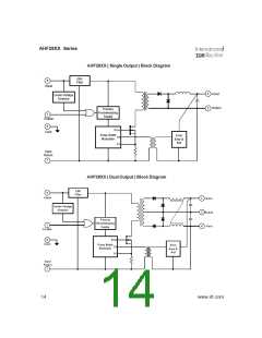
AHF28XX Series
Specifications
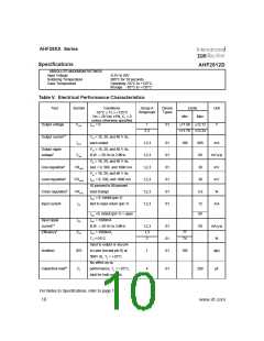
AHF2812D
ABSOLUTE MAXIMUM RATINGS
n
Input Voltage
-0.5V to 50V
Soldering Temperature
Case Temperature
300°C for 10 seconds
Operating -55°C to +125°C
Storage -65°C to +135°C
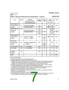
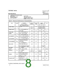
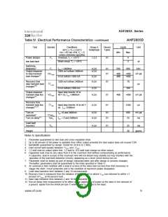
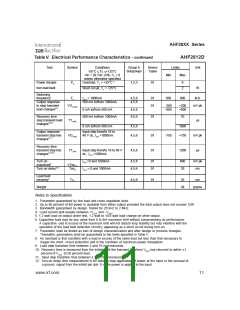
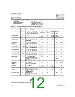
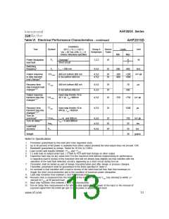
Table V. Electrical Performance Characteristics
Test
Symbol
Conditions
-55°C Tc +125°C
Vin = 28 Vdc ±5%, CL = 0
unless otherwise specified
IOUT = 0
Group A
Subgroups
Device
Types
Limits
Min Max
Unit
≤
≤
Output voltage
Output current1,2
VOUT
1
01
±11.88 ±12.12
±11.76 ±12.24
V
2,3
VIN = 16, 28, and 40 V dc,
each output
IOUT
1,2,3
1,2,3
1,2,3
1,2,3
1,2,3
1,2,3
01
01
01
01
01
01
100
900
60
mA
mV p-p
mV
Output ripple
voltage3
VIN = 16, 28, and 40 V dc,
B.W. = 20 Hz to 2 MHz
VIN = 16, 28, and 40 V dc,
Iout = 0, 500, and 1000 mA
VIN = 16, 28, and 40 V dc,
VRIP
Line regulation4
Load regulation4
Cross regulation5
Input current
VRLINE
VRLOAD
VRcros
IIN
30
I
OUT = 0, 500, and 1000 mA
30
mV
10 percent to 90 percent
load change
3.0
%
IOUT = 0, inhibit (pin 1)
tied to input return (pin 7)
12
60
mA
IOUT =0, inhibit (pin 1) = open
IOUT = 1000mA
Input ripple
current3,4
Efficiency4
IRIP
B.W. = 20 Hz to 2 MHz
IOUT = 1000mA,
1,2,3
1,3
2
01
01
01
50
mA p-p
%
EFF
77
74
TC =+25°C
Input to output or any pin
to case (except pin 6) at
500V dc, TC = +25°C
No effect on dc
Isolation
ISO
CL
1
4
100
M
Ω
Capacitive load6,7
performance, TC = +25°C,
total for both outputs
01
200
µF
For Notes to Specifications, refer to page 11
10
www.irf.com

 INFINEON [ Infineon ]