IRAM256-1067A
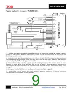
Typical Application Connection IRAM256-1067A
VB3 (1)
W, VS3 (2)
W
BOOT-STRAP
CAPACITORS
VB2 (5)
3-Phase AC
MOTOR
V, VS2 (6)
V
U
CURRENT SENSING CAN USE A
SINGLE SENSE RESISTOR OR PHASE
LEG SENSING AS SHOWN
VB1 (9)
U, VS1 (10)
V+
V+ (13)
DC BUS
CAPACITORS
ITRIP (16)
VRU (17)
PHASE LEG
CURRENT
SENSE
FLT/EN (18)
VRV (19)
HIN1 (20)
VRW (21)
HIN2 (22)
HIN3 (23)
LIN1 (24)
LIN2 (25)
CONTROLLER
LIN3 (26)
VTH (27)
VDD (28)
VSS (29)
15 V
5 V
Enable
100nF
0.1m
10m
1. Electrolytic bus capacitors should be mounted as close to the module bus terminals as possible to reduce
ringing and EMI problems. Additional high frequency ceramic capacitor mounted close to the module pins will
further improve performance.
2. In order to provide good decoupling between VCC-VSS and VB1,2,3-VS1,2,3 terminals, the capacitors shown
connected between these terminals should be located very close to the module pins. Additional high frequency
capacitors, typically 0.1µF, are strongly recommended.
3. Value of the boot-strap capacitors depends upon the switching frequency. Their selection should be made
based on IR design tip DN 98-2a, application note AN-1044 or Figure 9. Bootstrap capacitor value must be
selected to limit the power dissipation of the internal resistor in series with the VCC. (see maximum ratings Table
on page 3).
4. After approx. 2ms the FAULT is reset. (see Dynamic Characteristics Table on page 5).
5. PWM generator must be disabled within Fault duration to guarantee shutdown of the system, overcurrent
condition must be cleared before resuming operation.
9
www.irf.com
© 2014 International Rectifier
Submit Datasheet Feedback
May 14, 2014

 INFINEON [ Infineon ]