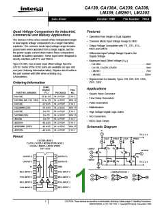
CA139, CA139A, CA239, CA339, LM339, LM2901, LM3302
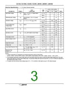
Electrical Specifications V+ = 5V, Unless Otherwise Specified
CA239, CA339, LM339
TEST
CONDITIONS
TEMP
( C)
o
PARAMETER
SYMBOL
MIN
TYP
MAX
5
UNITS
mV
Input Offset Voltage
V
V
= 1.4V, R = 0, Output Switch
T = 25
A
-
-
-
2
-
IO
REF
S
Point V 1.4V
Note 4
Note 4
9
mV
Differential Input Voltage
Saturation Voltage
V
-
36
V
Keep All Inputs ≥ 0V, or V- (if used)
ID
(Note 5)
V
V - = 1V, V + = 0V, I
≤ 4mA
T = 25
A
-
-
250
-
400
mV
mV
V
SAT
I
I
SINK
Note 4
700
Common Mode Input
Voltage Range
V
Note 6
T = 25
A
0
0
-
-
V+ -1.5
ICR
Note 4
-
V+ - 2
V
Input Offset Current
Input Bias Current
I
I + - I -
T = 25
A
5
50
nA
nA
nA
nA
mA
nA
µA
mA
V/mV
ns
IO
I
I
Note 4
-
-
150
I
I + or I - with Output in Linear Range
T = 25
A
-
25
-
250
IB
I
I
Note 4
-
400
Total Supply Current
I+
R
= ∞ on All Comparators
T = 25
-
0.8
0.1
-
2
-
L
A
Output Leakage Current
V + ≥ 1V, V - = 0V, V = 5V
T = 25
A
-
I
I
O
V + ≥ 1V, V - = 0V, V = 30V
Note 4
-
1
-
I
I
O
Output Sink Current
Voltage Gain
V - ≥ 1V, V + = 0V, V ≤ 1.5V
T = 25
6
50
-
16
200
300
I
I
O
A
A
R
≥ 15kΩ, V+ = 15V
L
T = 25
A
-
OL
Large Signal Response Time
T = 25
A
-
V = TTL Logic Swing, V
REF
= 1.4V,
I
V
= 5V, R = 5.1kΩ
RL
L
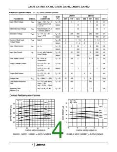
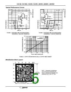
Response Time
(Figures 3, 4)
V
= 5V, R = 5.1kΩ
T = 25
-
1.3
-
µs
RL
L
A
NOTES:
4. Ambient Temperature (T ) applicable over operating temperature range as shown below.
A
o
o
o
o
o
o
o
o
CA139, CA139A = -55 C to 125 C; CA239 = -25 C to 85 C; CA339, LM339 = 0 C to 70 C; LM2901, LM3302 = -40 C to 85 C.
5. The comparator will provide a proper output state even if the positive swing of the inputs exceeds the power supply voltage level, if the other
input remains within the common mode voltage range. The low input voltage state must not be less than -0.3V (or 0.3V below the magnitude of
the negative power supply, if used).
6. The upper end of the common mode voltage range is (V+) - 1.5V, but either or both inputs can go to +30V without damage.
3

 INTERSIL [ Intersil ]