ISL705ARH, ISL705BRH, ISL705CRH, ISL706ARH, ISL706BRH, ISL706CRH
Absolute Maximum Ratings
Thermal Information
Supply Voltage Range . . . . . . . . . . . . . . . . . . . . . . . . . . . . . . . . -0.3V to 6.5V
Thermal Resistance (Typical)
8 Ld Flatpack Package (Notes 2, 3). . . . . .
θ
JA (°C/W)
140
θ
JC (°C/W)
Voltage on All Other Inputs . . . . . . . . . . . . . . . . . . . . . . . -0.3V to V + 0.3V
15
DD
ESD Rating
Maximum Junction Temperature . . . . . . . . . . . . . . . . . . . . . . . . . . . .+175°C
Storage Temperature Range. . . . . . . . . . . . . . . . . . . . . . . .-65°C to +150°C
Human Body Model (Tested per MIL-PRF-883 3015.7). . . . . . . . . .3.0kV
Machine Model (Tested per JESD22-A115C) . . . . . . . . . . . . . . . . . . 300V
Charged Device Model (Tested per JESD22-C110D) . . . . . . . . . . . .1.0kV
Latch Up (Tested per JESD-78C) . . . . . . . . . . . . . . . . . . . . . . Class 2, Level A
Recommended Operating Conditions
Temperature . . . . . . . . . . . . . . . . . . . . . . . . . . . . . . . . . . . . .-55°C to +125°C
Supply Voltage
ISL705ARH/BRH/CRH . . . . . . . . . . . . . . . . . . . . . . . . . . . . . 4.75V to 5.5V
ISL706ARH/BRH/CRH . . . . . . . . . . . . . . . . . . . . . . . . . . . . . 3.15V to 3.6V
CAUTION: Do not operate at or near the maximum ratings listed for extended periods of time. Exposure to such conditions may adversely impact product
reliability and result in failures not covered by warranty.
NOTES:
2. θ is measured with the component mounted on a low effective thermal conductivity test board in free air. See Tech Brief TB379 for details.
JA
3. For θJC, the “case temp” location is the center of the package underside.
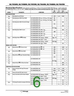
Electrical Specifications Unless otherwise specified V = 4.75V to 5.5V for the ISL705ARH/BRH/CRH, V = 3.15V to 3.6V for the
DD
DD
ISL706ARH/BRH/CRH T = -55°C to +125°C. Boldface limits apply over the ambient operating temperature range, -55°C to +125°C.
A
MIN
TYP
MAX
SYMBOL
PARAMETER
CONDITIONS
(Note 4) (Note 5) (Note 4) UNITS
POWER SUPPLY SECTION
V
Operating Supply Voltage (Note 6)
ISL705ARH/BRH/CRH
1.2
1.2
5
5.5
3.6
V
V
DD
ISL706ARH/BRH/CRH
ISL705ARH/BRH/CRH
ISL706ARH/BRH/CRH
3.3
I
Operating Supply Current
530
400
µA
µA
DD
RESET SECTION
V
Reset Threshold Voltage
ISL705ARH/BRH/CRH
ISL706ARH/BRH/CRH
ISL705ARH/BRH/CRH
ISL706ARH/BRH/CRH
4.50
3.00
20
4.65
3.08
40
4.75
3.15
V
V
RST
HYS
RST
V
Reset Threshold Voltage Hysteresis
mV
mV
ms
V
20
30
t
Reset Pulse Width
140
200
280
0.4
V
Reset Output Voltage
ISL705ARH/BRH, I
= 800µA
V
- 1.5
DD
OUT
SOURCE
ISL705ARH/BRH/CRH, I
= 3.2mA
V
SINK
ISL706ARH/BRH, I
= 500µA
0.8 x V
0.9
V
SOURCE
DD
ISL706ARH/BRH/CRH, I
= 1.2mA
0.3
0.3
V
SINK
ISL70XARH/CRH, V = 1.2V, I
= 100µA
V
DD
SINK
ISL70XBRH, V = 1.2V, I
= 4µA
V
DD SOURCE
I
Reset Output Leakage Current
ISL705CRH, V
= V
1
1
µA
µA
LEAK
OUT
OUT
DD
DD
ISL706CRH, V
= V
FN7662.0
September 15, 2011
5

 INTERSIL [ Intersil ]