HIN202E, HIN206E, HIN207E, HIN208E, HIN211E, HIN213E, HIN232E
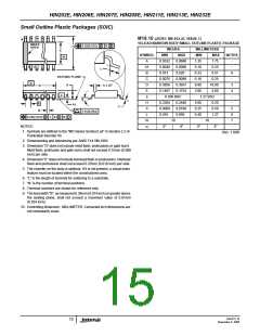
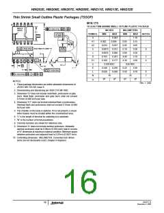
Thin Shrink Small Outline Plas tic Packages (TSSOP)
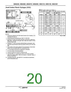
M16.173
N
16 LEAD THIN SHRINK SMALL OUTLINE PLASTIC PACKAGE
INDEX
AREA
0.25(0.010)
M
B M
E
INCHES
MIN
MILLIMETERS
E1
-B-
GAUGE
PLANE
SYMBOL
MAX
0.043
0.006
0.037
0.012
0.008
0.201
0.177
MIN
-
MAX
1.10
0.15
0.95
0.30
0.20
5.10
4.50
NOTES
A
A1
A2
b
-
-
0.002
0.033
0.0075
0.0035
0.193
0.169
0.05
0.85
0.19
0.09
4.90
4.30
-
1
2
3
-
L
0.25
0.010
0.05(0.002)
SEATING PLANE
A
9
-A-
c
-
D
D
3
-C-
E1
e
4
α
0.026 BSC
0.65 BSC
-
A2
e
A1
c
E
0.246
0.020
0.256
0.028
6.25
0.50
6.50
0.70
-
b
0.10(0.004)
L
6
0.10(0.004) M
C
A M B S
N
16
16
7
o
o
o
o
0
8
0
8
-
α
NOTES:
Rev. 1 2/02
1. These package dimensions are within allowable dimensions of
JEDEC MO-153-AB, Issue E.
2. Dimensioning and tolerancing per ANSI Y14.5M-1982.
3. Dimension “D” does not include mold flash, protrusions or gate
burrs. Mold flash, protrusion and gate burrs shall not exceed
0.15mm (0.006 inch) per side.
4. Dimension “E1” does not include interlead flash or protrusions.
Interlead flash and protrusions shall not exceed 0.15mm (0.006
inch) per side.
5. The chamfer on the body is optional. If it is not present, a visual
index feature must be located within the crosshatched area.
6. “L” is the length of terminal for soldering to a substrate.
7. “N” is the number of terminal positions.
8. Terminal numbers are shown for reference only.
9. Dimension “b” does not include dambar protrusion. Allowable
dambar protrusion shall be 0.08mm (0.003 inch) total in excess
of “b” dimension at maximum material condition. Minimum space
between protrusion and adjacent lead is 0.07mm (0.0027 inch).
10. Controlling dimension: MILLIMETER. Converted inch dimen-
sions are not necessarily exact. (Angles in degrees)
FN4315.16
16
November 4, 2005

 INTERSIL [ Intersil ]