Thermal Specifications and Design Considerations
With a properly designed and characterized thermal solution, it is anticipated that the
TCC would only be activated for very short periods of time when running the most
power intensive applications. The processor performance impact due to these brief
periods of TCC activation is expected to be so minor that it would be immeasurable. An
under-designed thermal solution that is not able to prevent excessive activation of the
TCC in the anticipated ambient environment may cause a noticeable performance loss,
and in some cases may result in a TC that exceeds the specified maximum temperature;
this may affect the long-term reliability of the processor. In addition, a thermal solution
that is significantly under-designed may not be capable of cooling the processor even
when the TCC is active continuously. Refer to the appropriate processor Thermal and
Mechanical Design Guidelines (see Section 1.2) for information on designing a thermal
solution.
The duty cycle for the TCC, when activated by the Thermal Monitor, is factory
configured and cannot be modified. The Thermal Monitor does not require any
additional hardware, software drivers, or interrupt handling routines.
5.2.2
Thermal Monitor 2
The Pentium 4 processor also supports an additional power reduction capability known
as Thermal Monitor 2. This mechanism provides an efficient means for limiting the
processor temperature by reducing the power consumption within the processor.
When Thermal Monitor 2 is enabled, and a high temperature situation is detected, the
Thermal Control Circuit (TCC) will be activated. The TCC causes the processor to adjust
its operating frequency (via the bus multiplier) and input voltage (via the VID signals).
This combination of reduced frequency and VID results in a reduction to the processor
power consumption.
A processor enabled for Thermal Monitor 2 includes two operating points, each
consisting of a specific operating frequency and voltage. The first operating point
represents the normal operating condition for the processor. Under this condition, the
core-frequency-to-FSB multiple used by the processor is that contained in the
IA32_PERF_STS MSR and the VID is the one specified in Table 4. These parameters
represent normal system operation.
The second operating point consists of both a lower operating frequency and voltage.
When the TCC is activated, the processor automatically transitions to the new
frequency. This transition occurs very rapidly (on the order of 5 µs). During the
frequency transition, the processor is unable to service any bus requests, and
consequently, all bus traffic is blocked. Edge-triggered interrupts are latched and kept
pending until the processor resumes operation at the new frequency.
Once the new operating frequency is engaged, the processor will transition to the new
core operating voltage by issuing a new VID code to the voltage regulator. The voltage
regulator must support dynamic VID steps in order to support Thermal Monitor 2.
During the voltage change, it will be necessary to transition through multiple VID codes
to reach the target operating voltage. Each step will likely be one VID table entry (see
Table 4). The processor continues to execute instructions during the voltage transition.
Operation at the lower voltage reduces the power consumption of the processor.
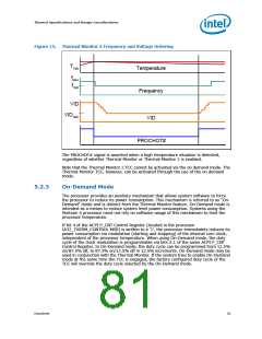
A small amount of hysteresis has been included to prevent rapid active/inactive
transitions of the TCC when the processor temperature is near its maximum operating
temperature. Once the temperature has dropped below the maximum operating
temperature, and the hysteresis timer has expired, the operating frequency and
voltage transition back to the normal system operating point. Transition of the VID code
will occur first, in order to insure proper operation once the processor reaches its
normal operating frequency. Refer to Figure 15 for an illustration of this ordering.
80
Datasheet

 INTEL [ INTEL ]