Balanced Technology Extended (BTX) Boxed Processor Specifications
Note:
The boxed processor’s TMA requires a constant +12 V supplied to pin 2 and does not
support variable voltage control or 3-pin PWM control.
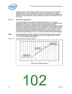
The power header on the baseboard must be positioned to allow the TMA power cable
to reach it. The power header identification and location should be documented in the
platform documentation, or on the system board itself. Figure 31 shows the location of
the fan power connector relative to the processor socket. The baseboard power header
should be positioned within 4.33 inches from the center of the processor socket.
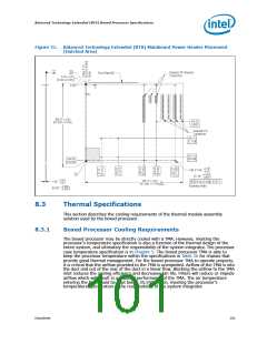
Figure 30.
Boxed Processor TMA Power Cable Connector Description
Signal
Pin
Straight square pin, 4-pin terminal housing with
polarizing ribs and friction locking ramp.
1
2
3
4
GND
+12 V
0.100" pitch, 0.025" square pin width.
SENSE
CONTROL
Match with straight pin, friction lock header on
mainboard.
3 4
1 2
Boxed Proc PwrCable
Table 36.
TMA Power and Signal Specifications
Description
Min
Typ
Max
Unit
Notes
+12 V: 12 volt fan power supply
10.2
12
13.8
V
IC:
Peak Fan current draw
Fan start-up current draw
Fan start-up current draw maximum duration
—
—
—
1.0
—
1.5
2.0
1.0
A
A
—
Second
pulses per
fan
1
SENSE: SENSE frequency
—
2
—
revolution
2,3
CONTROL
21
25
28
kHz
NOTES:
1. Baseboard should pull this pin up to 5 V with a resistor.
2. Open Drain Type, Pulse Width Modulated.
3. Fan will have a pull-up resistor to 4.75 V, maximum 5.25 V.
100
Datasheet

 INTEL [ INTEL ]