Signal Definitions
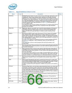
Table 5-1.
Signal Definitions (Sheet 5 of 8)
Name
Type
Description
Notes
IGNNE#
I
IGNNE# (Ignore Numeric Error) is asserted to force the processor to ignore a
numeric error and continue to execute noncontrol floating-point instructions. If
IGNNE# is deasserted, the processor generates an exception on a noncontrol
floating-point instruction if a previous floating-point instruction caused an error.
IGNNE# has no effect when the NE bit in control register 0 (CR0) is set.
2
IGNNE# is an asynchronous signal. However, to ensure recognition of this signal
following an I/O write instruction, it must be valid along with the TRDY# assertion of
the corresponding I/O write bus transaction.
INIT#
I
I
INIT# (Initialization), when asserted, resets integer registers inside all processors
without affecting their internal caches or floating-point registers. Each processor then
begins execution at the power-on Reset vector configured during power-on
configuration. The processor continues to handle snoop requests during INIT#
assertion. INIT# is an asynchronous signal and must connect the appropriate pins of
all processor FSB agents.
2
2
LINT[1:0]
LINT[1:0] (Local APIC Interrupt) must connect the appropriate pins of all FSB
agents. When the APIC functionality is disabled, the LINT0/INTR signal becomes
INTR, a maskable interrupt request signal, and LINT1/NMI becomes NMI, a
nonmaskable interrupt. INTR and NMI are backward compatible with the signals of
®
those names on the Pentium processor. Both signals are asynchronous.
These signals must be software configured via BIOS programming of the APIC
register space to be used either as NMI/INTR or LINT[1:0]. Because the APIC is
enabled by default after Reset, operation of these pins as LINT[1:0] is the default
configuration.
LL_ID[1:0]
LOCK#
O
The LL_ID[1:0] signals are used to select the correct loadline slope for the processor.
The Dual-Core Intel Xeon Processor 5000 series pull these signals to ground on the
package for a logic 0 as these signals are not connected to the processor die. A logic
1 is a no-connect on the Dual-Core Intel Xeon Processor 5000 series package.
I/O
LOCK# indicates to the system that a transaction must occur atomically. This signal
must connect the appropriate pins of all processor FSB agents. For a locked series of
transactions, LOCK# is asserted from the beginning of the first transaction to the end
of the last transaction.
3
When the priority agent asserts BPRI# to arbitrate for ownership of the processor
FSB, it will wait until it observes LOCK# deasserted. This enables symmetric agents
to retain ownership of the processor FSB throughout the bus locked operation and
ensure the atomicity of lock.
MCERR#
I/O
MCERR# (Machine Check Error) is asserted to indicate an unrecoverable
error without a bus protocol violation. It may be driven by all processor
FSB agents.
MCERR# assertion conditions are configurable at a system level. Assertion
options are defined by the following options:
• Enabled or disabled.
• Asserted, if configured, for internal errors along with IERR#.
• Asserted, if configured, by the request initiator of a bus transaction
after it observes an error.
• Asserted by any bus agent when it observes an error in a bus
transaction.
For more details regarding machine check architecture, refer to the IA-32 Software
Developer’s Manual, Volume 3: System Programming Guide.
MS_ID[1:0]
PROCHOT#
O
O
These signals are provided to indicate the Market Segment for the processor and
may be used for future processor compatibility or for keying. The Dual-Core Intel
Xeon Processor 5000 series pull these signals to ground on the package for a logic 0
as these signals are not connected to the processor die. A logic 1 is a no-connect on
the Dual-Core Intel Xeon Processor 5000 series package.
PROCHOT# (Processor Hot) will go active when the processor’s temperature
monitoring sensor detects that the processor has reached its maximum safe
operating temperature. This indicates that the Thermal Control Circuit (TCC) has
been activated, if enabled. The TCC will remain active until shortly after the
processor deasserts PROCHOT#. See Section 6.2.3 for more details. PROCHOT#
from each processor socket should be kept separated and not tied together on
platform designs.
Dual-Core Intel® Xeon® Processor 5000 Series Datasheet
65

 INTEL [ INTEL ]