Electrical Characteristics
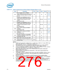
firmware, the Max value of t234 and t298 is 99 ms. Without the installation of the
firmware, the Max value is 4 RTC clocks.
17.
18.
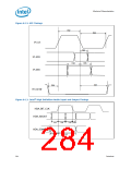
RSMRST# must de-assert at or before LAN_RST# de-assertion.
Measured from VccLAN3_3 or VccLAN1_1 power within voltage specification (which ever is
later in time) to LAN_RST# = (Vih+Vil)/2. It is acceptable to use an RC circuit sourced
from VccLAN3_3 to create LAN_RST#. The rising edge of LAN_RST# needs to be a clean,
monotonic edge for frequency content below 10 MHz.
19.
20.
If Integrated LAN is supported, LAN_RST# must be de-asserted at or before PWROK
assertion.
If Integrated LAN is not supported, LAN_RST# should be tied to ground and must never
de-assert.
21.
22.
RSMRST# falling edge must transition to 0.8 V or less before VccSus3_3 drops to 2.1 V
If bit 0 of Section 13.8.1.3 is set to a 1, SLP_S5# will not be de-asserted until a wake
event is detected. If bit 0 is set to 0, SLP_S5# will de-assert within the specification listed
in the table.
23.
t294 is not applied to V5REF. V5REF timings are bounded by power sequencing. t294
applies during S0 to S3/S4/S5 and S0 to G3 transitions.
t307 is applicable in S0 to Sx transitions.
A Power rail is considered to be inactive when the rail is at its nominal voltage minus 5% or
less.
24.
25.
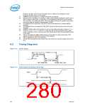
8.5
Timing Diagrams
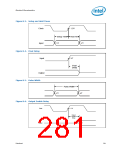
Figure 8-1. Clock Timing
Period
High Time
2.0V
0.8V
Low Time
Fall Time
Rise Time
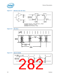
Figure 8-2. Valid Delay from Rising Clock Edge
Clock
1.5V
Valid Delay
Output
VT
280
Datasheet

 INTEL [ INTEL ]