Package Mechanical Specifications
3.2
3.3
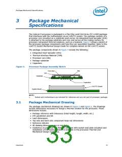
Processor Component Keep-Out Zones
The processor may contain components on the substrate that define component keep-
out zone requirements. A thermal and mechanical solution design must not intrude into
the required keep-out zones. Decoupling capacitors are typically mounted to either the
topside or land-side of the package substrate. See Figure 5 and Figure 6 for keep-out
zones. The location and quantity of package capacitors may change due to
manufacturing efficiencies but will remain within the component keep-in.
Package Loading Specifications
Table 20 provides dynamic and static load specifications for the processor package.
These mechanical maximum load limits should not be exceeded during heatsink
assembly, shipping conditions, or standard use condition. Also, any mechanical system
or component testing should not exceed the maximum limits. The processor package
substrate should not be used as a mechanical reference or load-bearing surface for
thermal and mechanical solution. The minimum loading specification must be
maintained by any thermal and mechanical solutions.
.
Table 20.
Processor Loading Specifications
Parameter
Minimum
Maximum
Notes
1, 2, 3
Static
80 N [17 lbf]
—
311 N [70 lbf]
756 N [170 lbf]
1, 3, 4
Dynamic
NOTES:
1. These specifications apply to uniform compressive loading in a direction normal to the
processor IHS.
2. This is the maximum force that can be applied by a heatsink retention clip. The clip must also
provide the minimum specified load on the processor package.
3. These specifications are based on limited testing for design characterization. Loading limits are
for the package only and do not include the limits of the processor socket.
4. Dynamic loading is defined as an 11 ms duration average load superimposed on the static load
requirement.
3.4
Package Handling Guidelines
Table 21 includes a list of guidelines on package handling in terms of recommended
maximum loading on the processor IHS relative to a fixed substrate. These package
handling loads may be experienced during heatsink removal.
Table 21.
Package Handling Guidelines
Parameter
Maximum Recommended
Notes
1, 2
Shear
Tensile
Torque
311 N [70 lbf]
111 N [25 lbf]
2, 3
2, 4
3.95 N-m [35 lbf-in]
NOTES:
1. A shear load is defined as a load applied to the IHS in a direction parallel to the IHS top surface.
2. These guidelines are based on limited testing for design characterization.
3. A tensile load is defined as a pulling load applied to the IHS in a direction normal to the IHS
surface.
4. A torque load is defined as a twisting load applied to the IHS in an axis of rotation normal to the
IHS top surface.
Datasheet
37

 INTEL [ INTEL ]