TLE9263QX
High Speed CAN Transceiver
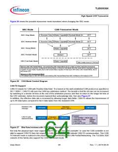
Figure 26 shows the possible transceiver mode transitions when changing the SBC mode.
SBC Mode
CAN Transceiver Mode
SBC Stop Mode
Receive Only Wake Capable Normal Mode
OFF
OFF
SBC Normal Mode
SBC Sleep Mode
SBC Restart Mode
SBC Fail-Safe Mode
Receive Only Wake Capable Normal Mode
Wake Capable
OFF
OFF
Woken1
Wake Capable
1after a wake event on CAN Bus
Behavior after SBC Restart Mode - not coming from SBC Sleep Mode due to a wake up of the respective transceive:r
If the transceivers had been configured to Normal Mode, or Receive Only Mode, then the mode will be changed to Wake
Capable. If it was Wake Capable, then it will remainWake Capable. If it had been OFF before SBC Restart Mode, then it
will remain OFF.
Behavior in SBC Development Mode:
CAN default value in SBC INIT MODE and entering SBC Normal Mode from SBC Init Mode is ON instead of OFF.
Figure 26 CAN Mode Control Diagram
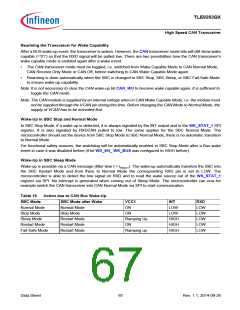
CAN FD Support
CAN FD stands for ‘CAN with Flexible Data Rate’. It is based on the well established CAN protocol as specified in
ISO 11898-1. CAN FD still uses the CAN bus arbitration method. The benefit is that the bit rate can be increased
by switching to a shorter bit time at the end of the arbitration process and then to return to the longer bit time at
the CRC delimiter, before the receivers transmit their acknowledge bits. See also Figure 27.
In addition, the effective data rate is increased by allowing longer data fields. CAN FD allows the transmission of
up to 64 data bytes compared to the 8 data bytes from the standard CAN.
Standard CAN
message
Data phase
(Byte 0 – Byte 7)
CAN Header
CAN Header
CAN Footer
Example:
- 11bit identifier + 8Byte data
CAN FD with
reduced bit time
Data phase
(Byte 0 – Byte 7)
CAN Footer
- Arbitration Phase
- Data Phase
500kbps
2Mbps
ꢂaverage bit rate
1.14Mbps
Figure 27 Bite Rate Increase with CAN FD vs. Standard CAN
Not only the physical layer must support CAN FD but also the CAN controller. In case the CAN controller is not
able to support CAN FD then the respective CAN node must at least tolerate CAN FD communication. This CAN
FD tolerant mode is realized in the physical layer in combination with CAN Partial Networking. The TLE926x-3QX
variants of this family also support the CAN FD tolerant mode.
Data Sheet
64
Rev. 1.1, 2014-09-26

 INFINEON [ Infineon ]