TLE9263QX
High Speed CAN Transceiver
10
High Speed CAN Transceiver
10.1
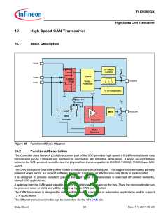
Block Description
VCAN
VCC1
SPI Mode
Control
RTXD
Driver
CANH
Output
TXDCAN
Stage
Temp.-
Protection
+
CANL
timeout
To SPI diagnostic
VCAN
VBIAS = 2.5V
VCC1
RXDCAN
MUX
Receiver
Vs
Wake
Receiver
Figure 25 Functional Block Diagram
10.2
Functional Description
The Controller Area Network (CAN) transceiver part of the SBC provides high-speed (HS) differential mode data
transmission (up to 2 Mbaud) and reception in automotive and industrial applications. It works as an interface
between the CAN protocol controller and the physical bus lines compatible to ISO/DIS 11898-2, 11898-5 and SAE
J2284.
The CAN transceiver offers low power modes to reduce current consumption. This supports networks with partially
powered down nodes. To support software diagnostic functions, a CAN Receive-only Mode is implemented.
It is designed to provide excellent passive behavior when the transceiver is switched off (mixed networks,
clamp15/30 applications).
A wake-up from the CAN wake capable mode is possible via a message on the bus. Thus, the microcontroller can
be powered down or idled and will be woken up by the CAN bus activities.
The CAN transceiver is designed to withstand the severe conditions of automotive applications and to support
12 V applications.
The different transceiver modes can be controlled via the SPI CAN bits.
Data Sheet
63
Rev. 1.1, 2014-09-26

 INFINEON [ Infineon ]