TLE 6244X
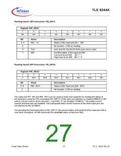
Reading Input1 (SPI Instruction: RD_INP1)
:
Register INP_REG1
7
6
5
0
4
3
2
1
0
IN8
Test
IN5
IN4
IN3
IN2
IN1
Bit
0..4
5
Name
Description
IN(1...5)
Status of the input pins IN1... IN5
No function: LOW on reading
6
Test
IN8
µsec-test-bit, the bit D8 of the µsec-bus is read
7
Inverted status of the input pin IN8:
Low level at pin IN8: Bit 7 = 1
High level at pin IN8: Bit 7 = 0
Reading Input2 (SPI Instruction: RD_INP2):
Register INP_REG2
7
6
5
4
3
2
1
0
0
IN15
IN14
IN13
IN12
IN11
IN10
IN9
Bit
0..6
7
Name
Description
IN9...IN15
Status of the input pins IN9...IN15
No function: LOW on reading
The input pins IN1..IN5 and IN8...IN15 can be used as input port expander by reading the status of
the input pins using the SPI-commands RD_INP1/2. If the µsec-bus-interface is enabled (BMUX=0) the
pull-up current sources at the input IN1..5 and IN9..15 are disabled. If BMUX=1 the pullup current
sources at these pins are enabled. The pull-up/pull-down current sources of the other input pins are
not effected by the bit BMUX.
On executing the read instruction on RD_INP1/2, the present status (not latched) of the input pins INx is
read back (exception: bit IN8 represents the inverted status of input pin IN8).
Final Data Sheet
27
V4.2, 2003-08-29

 INFINEON [ Infineon ]