TLD7002-16ES
Datasheet
9 Communication interface
9.2.3
Electrical characteristics
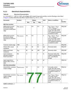
Table 49
Electrical Characteristics
VS = 6 V to 20 V, TJ = -40°C to +150°C, all voltages with respect to ground, positive currents flowing as described
in Figure 2 (unless otherwise specified). Typical values: VS = 9 V, TJ = 25°C
Parameter
Symbol
Values
Typ.
Unit
Note or condition
P-
Number
Min.
Max.
HSLI bus receiver
Differential receiver:
threshold voltage,
recessive to dominant
edge
Vdiff_rd(active)
–
0.8
0.9
V
Vdiff = VHSLIH - VHSLIL
;
PRQ-504
PRQ-505
- 12 V < VCM(HSLI)
<
12 V; init mode, active
mode, fail-safe mode,
OTP programming and
emulation modes
Differential receiver:
threshold voltage,
dominant to recessive
edge
Vdiff_dr(active)
0.5
0.6
–
V
Vdiff = VHSLIH - VHSLIL
- 12 V < VCM(HSLI)
;
<
12 V; init mode, active
mode, fail-safe mode,
OTP programming and
emulation modes
Common mode range CMR
-12
20
–
12
50
V
–
PRQ-506
PRQ-507
HSLIH, HSLIL input
resistance
Ri
40
kΩ
Recessive state
Differential input
Rdiff
DRi
40
-3
80
–
100
3
kΩ
Recessive state
PRQ-508
PRQ-509
resistance
Input resistance
deviation between
HSLIH and HSLIL
ꢀ
Recessive state, Not
subject to production
test - specified by
design
Input capacitance
HSLIH, HSLIL versus
GND
Ci
–
20
–
40
pF
V
–
PRQ-510
PRQ-511
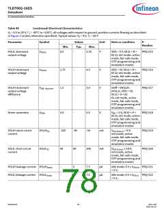
HSLI bus transmitter
HSLIH/HSLIL recessive VHSLIH/L(active) 2.0
output voltage
3.0
init mode, active
mode, fail-safe mode,
OTP programming and
emulation modes; no
load
HSLIH/HSLIL recessive Vdiff_r(active)
output voltage
difference
-500
–
50
mV
Vdiff = VHSLIH - VHSLIL
;
PRQ-513
init mode, active
mode, fail-safe mode,
OTP programming and
emulation modes; no
load
(table continues...)
Datasheet
77
Rev.1.00
2022-05-03

 INFINEON [ Infineon ]