TLD7002-16ES
Datasheet
9 Communication interface
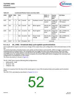
Table 30
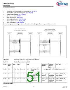
(continued) Master frame overview table
SYNC ADDR MRC
ESS
DLC
FUN
DATA_0 ... Ouptut
ACK Byte
DATA_n
Status
Byte
0x55
0x55
0x55
...
0x3
0x4
0x5
...
x
x
x
x
x
x
0x3 4 words 0x3
0x4 8 words 0x4
0x5 12 words 0x5
Hardware control data by the Diagnostic CRC-3, MODE, RC,
master
feedback
(slave)
TER (slave)
Write register
Read register
data by the Diagnostic CRC-3, MODE, RC,
master
feedback
(slave)
TER (slave)
data by the Diagnostic CRC-3, MODE, RC,
slave
feedback
(slave)
TER (slave)
... ... 0x6 16 words 0x6
Power mode
change
data by the Diagnostic CRC-3, MODE, RC,
master
feedback
(slave)
TER (slave)
0x55
0x1F
x
x
0x7 32 words 0x7
reserved
9.1.11.2
DC_SYNC - broadcast duty cycle update synchronization
Some applications require a synchronous change of the output duty cycle configuration of all connected slaves on the
bus.
The protocol provides a broadcast duty cycle update synchronization command (DC_SYNC) to trigger a synchronous
sampling event at multiple slaves. The sampling event can trigger the duty cycle update process, where the duty
cycle data from the shadow register is transferred to the hardware control register synchronized to the start of the
next PWM period. An updated output channel completes the actual PWM pulse before changing to the new duty cycle
configuration to avoid glitches on the output.
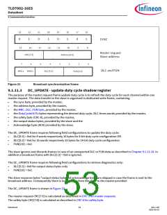
The frame description is shown in Figure 21.
The DC_SYNC frame requires following field configurations:
•
•
•
Address[4:0] = 0x00
DLC[5:3] = 0x0
FUN[2:0] = 0x0
There is no response from the slave to the master given in case of the broadcast duty cycle update synchronization
frame.
The CRC [7:5] is calculated as described in Chapter 9.1.11.11.
Datasheet
52
Rev.1.00
2022-05-03

 INFINEON [ Infineon ]