TLD7002-16ES
Datasheet
7 Load Diagnostic
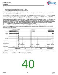
Open load on OUT1
ACTIVE ON
ACTIVE ON
OUT1
OUTn
ERRn
OL FLAG
RECON_FLAG
GPIN
RECONFIRMATION CYCLE
Device Status
ACTIVE
INIT
ACTIVE
INIT
ACTIVE
treconf
2+nDebounce PWM
treconf
2+nDebounce PWM
1+nDebounce PWM
Normal
Operation
OUT1 Open Load
OUTn Normal Operation
Normal
Operation
Application
Status
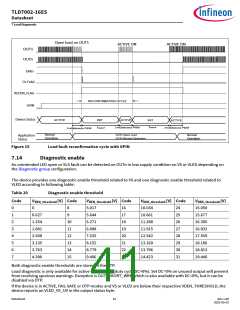
Figure 15
Load fault reconfirmation cycle with GPIN
7.14
Diagnostic enable
An unintended LED open or SLS fault can be detected on OUTn in low supply condition on VS or VLED depending on
the Diagnostic group configuration.
The device provides one diagnostic enable threshold related to VS and one diagnostic enable threshold related to
VLED according to following table:
Table 20
Diagnostic enable threshold
VDEN_threshold [V] Code VDEN_threshold [V] Code
Code
VDEN_threshold [V] Code
VDEN_threshold [V]
15.050
0
1
2
3
4
5
6
7
0
8
5.017
5.644
6.271
6.898
7.525
8.152
8.779
9.406
16
17
18
19
20
21
22
23
10.034
10.661
11.288
11.915
12.542
13.169
13.796
14.423
24
25
26
27
28
29
30
31
0.627
1.254
1.881
2.508
3.135
3.763
4.390
9
15.677
10
11
12
13
14
15
16.305
16.932
17.559
18.186
18.813
19.440
Both diagnostic enable thresholds are stored in the OTP.
Load diagnostic is only available for active-ON channel (duty cycle DC>0ꢀ). Set DC=0ꢀ on unused output will prevent
from receiving spurious warnings. Exception is OUT_SHORT_WRN which is also available with DC=0ꢀ, but it can be
disabled via OTP.
If the device is in ACTIVE, FAIL-SAFE or OTP modes and VS or VLED are below their respective VDEN_THRESHOLD, the
device reports an VLED_VS_UV in the output status byte.
Datasheet
41
Rev.1.00
2022-05-03

 INFINEON [ Infineon ]