TDA5235
Functional Description
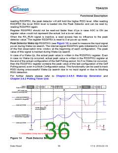
reading RSSIPRX, the peak detector will still hold the higher RSSI level. After reading
RSSIPRX the lower RSSI level is loaded into the Peak Detector and can be read by
reading RSSIPRX again.
Register RSSIPRX should not be read-out faster than 41µs in case AGC is ON (as
register value would not represent the actual, but a lower value).
When the RX_RUN signal is inactive, a read access has no influence to the peak
detector value. The register RSSIPRX is reset to 0 at power up reset.
Peak Detector Wake-Up RSSIPWU (see Figure 10) is used to measure the input signal
power during Wake-Up search. The internal signal RSSIPWU gets initialized to 0 at start
of the first observation time window at the beginning of each configuration. The peak
value of this signal is tracked during Wake-Up search.
In case of a Wake-Up, the actual peak value is written in the RSSIPWU register. Even
in case no Wake-Up occurred, actual peak value is written in the RSSIPWU register at
the end of the actual configuration of the Self Polling period. So if no Wake-Up occurred,
then the RSSIPWU register contains the peak value of the last configuration of the Self
Polling period, even in a Multi-Configuration setup. This functionality can be used to track
RSSI during unsuccessful Wake-Up search due to no input signal or due to blocking
RSSI detection.
For further details please refer to Chapter 2.4.8.5 Wake-Up Generator and
Chapter 2.6.2 Polling Timer Unit.
Input
Data Pattern
Dn
-1
Dn Dn Dn
+1 +2 +3
Run-In
Run-In
TSI D0 D1
Noise
TSI D0 D1
Dn
EOM
Noise
....
....
....
SPI read out
RSSIPPL&RSSIPRX
internal RSSIPPL
RSSIPPL Register
internal RSSI
FSYNC clears the
internal RSSIPPL
internal RSSIPRX =
RSSIPRX Register
internal RSSI
*1
*1
*1
*1
SPI
Reset
FSync
n = PKBITPOS
EOM
FSync
*1 Computation Delay due to filtering and signal calculation.
Figure 14
Peak Detector Behavior
Data Sheet
36
V1.0, 2010-02-19

 INFINEON [ Infineon ]