TDA5235
Reference
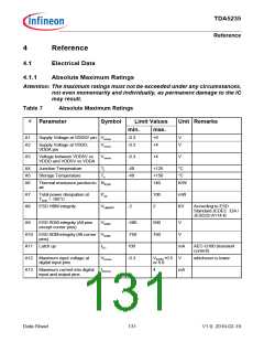
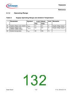
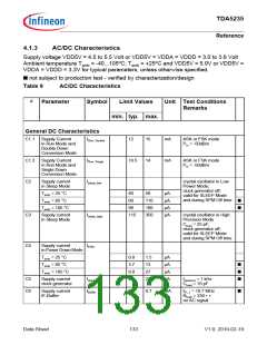
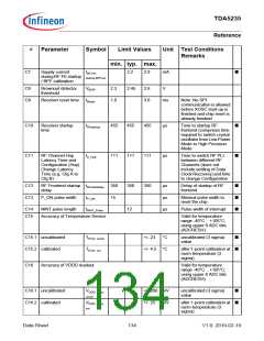
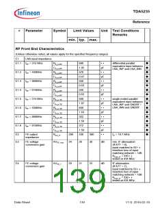
#
Parameter
Symbol
Limit Values
Unit Test Conditions
Remarks
min. typ. max.
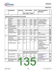
General RF Characteristics (overall)
D1
Frequency
Range 1
Range 2
Range 3
Range 4
fband_1
fband_2
fband_3
fband_4
fstep
300
425
863
902
10.5
320
450
870
928
MHz
MHz
MHz
MHz
Hz
1st Local Oscillator
Low Side LO-injection
and High Side LO-
injection allowed;
See also Chapter 3
D2
D3
Frequency step of
Sigma-Delta PLL
fstep = fXTAL / 221
■
ASK Demodulation
Data Rate
Rdata
0.5
-10
50
40
kchip/s
■
■
■
■
Data rate tol.
Rdata_tol
mASK
+10
100
100
%
%
%
Modulation index
ASK
mOOK
99
ON-OFF keying
D4
FSK Demodulation
Data Rate
Rdata
0.5
-10
1
112
+10
64
kchip/s including tolerance
%
■
■
■
Data rate tol.
Rdata_tol
Frequency deviation Δf
kHz
frequency deviation
zero-peak
Modulation index
mFSK
1.0
m = frequency_
■
deviationzero-peak
/
maximum_occuring_data
_frequency;
m >= 1.25 is
recommended at small
frequency deviation
D5
Decoding schemes
Manchester, differential Manchester,
Bi-phase Mark / Bi-phase Space
Duty cycle ASK
Duty cycle FSK
Tchip
Tdata
/
35
55
%
see Chapter 2.7.2
Definition C
■
■
Tchip
/
45
55
%
see Chapter 2.7.2
Tdata
Definition B
D6
Overall noise figure
Noise figure
RF input matched to 50 Ω
@ Tamb = 25 °C
NF
6
8
dB
■
Data Sheet
135
V1.0, 2010-02-19

 INFINEON [ Infineon ]