TC1767
Electrical Parameters
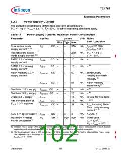
5.2.6
Power Supply Current
The default test conditions (differences explicitly specified) are:
DD = 1.58 V, VDDP = 3.47 V, Tj=150oC. All other operating conditions apply.
V
Table 17
Power Supply Currents, Maximum Power Consumption
Parameter
Symbol
Values
Unit Note /
Test Condition
Min. Typ. Max.
Core active mode
supply current 1) 2)
IDD
CC –
–
–
–
–
–
330
230
10
mA
mA
mA
mA
f
CPU=133 MHz
fCPU/fSYS = 2:1
Realistic core active
–
VDD = 1.53 V,
mode supply current 3)4)
TJ = 150oC
FADC 3.3 V analog
supply current
IDDMF
IDDAF
CC –
CC –
–
4)
FADC 1.5 V analog
supply current
10
–
Flash memory 3.3 V
supply current
IDDFL3R CC –
60
mA continuously
reading the Flash
memory 5)
IDDFL3E CC –
–
61
mA Flash memory
erase-verify6)
4)
Oscillator 1.5 V supply IDDOSC CC
Oscillator 3.3 V supply IDDOSC3 CC
–
–
–
–
–
–
3
mA
mA
–
–
4)
–
–
10
15
16
34
LVDS 3.3 V supply
ILVDS
IDDP
mA in total for two pairs
4) 7)
Pad currents,sum of
CC –
mA
mA
–
V
DDP 3.3 V supplies
IDDP_FP CC –
I
DDP including Data
Flash programming
current 4) 8)
ADC 5 V power supply IDDM
CC –
SR –
2
3
mA ADC0 / 1
Maximum Average
Power Dissipation1)
PD
820 990
mW worst case
TA = 125oC,
PD × RΘJA < 25oC
1) Infineon Power Loop: CPU and PCP running, all peripherals active. The power consumption of each custom
application will most probably be lower than this value, but must be evaluated separately..
2) The IDD maximum value is 275 mA at fCPU = 80 MHz, constant TJ = 150oC, for the Infineon Max Power Loop.
The dependency in this range is, at constant junction temperature, linear.
fCPU/fSYS = 1:1 mode.
Data Sheet
98
V1.3, 2009-09

 INFINEON [ Infineon ]