C167CR
C167SR
Bus Cycle Control via READY Input
The duration of an external bus cycle can be controlled by the external circuitry via the
READY input signal.
Synchronous READY permits the shortest possible bus cycle but requires the input
signal to be synchronous to the reference signal CLKOUT.
Asynchronous READY puts no timing constraints on the input signal but incurs one
waitstate minimum due to the additional synchronization stage.
Table 17
READY Timing (Operating Conditions apply)
Parameter
Symbol
Limits
max.
Unit
min.
tc25 CC 12
Input setup time to CLKOUT rising edge
Valid for: READY input
–
–
–
ns
ns
ns
Input hold time after CLKOUT rising edge
Valid for: READY input
Asynchronous READY input low time6)
tc26 CC 0
tc27 CC tc5 + tc25
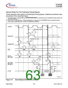
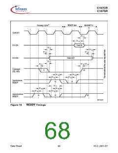
Notes (Valid also for Figure 19)
4)
Cycle as programmed, including MCTC waitstates (Example shows 0 MCTC WS).
READY sampled HIGH at this sampling point generates a READY controlled waitstate,
READY sampled LOW at this sampling point terminates the currently running bus cycle.
These timings are given for test purposes only, in order to assure recognition at a specific clock edge.
If the Asynchronous READY signal does not fulfill the indicated setup and hold times with respect to CLKOUT,
it must fulfill tc27 in order to be safely synchronized.
5)
6)
Proper deactivation of READY is guaranteed if READY is deactivated in response to the trailing (rising) edge
of the corresponding command (RD or WR).
Multiplexed bus modes have a MUX waitstate added after a bus cycle, and an additional MTTC waitstate may
be inserted here. For a multiplexed bus with MTTC waitstate this delay is 2 CLKOUT cycles, for a
demultiplexed bus without MTTC waitstate this delay is zero.
If the next following bus cycle is READY controlled, an active READY signal must be disabled before the first
valid sample point for the next bus cycle. This sample point depends on the MTTC waitstate of the current
cycle, and on the MCTC waitstates and the ALE mode of the next following cycle. If the current cycle uses a
multiplexed bus the intrinsic MUX waitstate adds another CLKOUT cycle to the READY deactivation time.
7)
8)
Data Sheet
63
V3.2, 2001-07

 INFINEON [ Infineon ]