OptiMOSTM5ꢀPower-Transistor,ꢀ60ꢀV
ISZ0703NLS
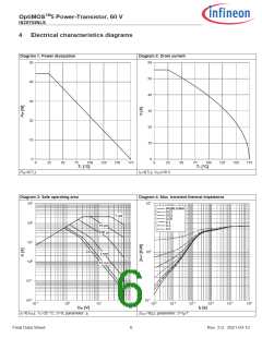
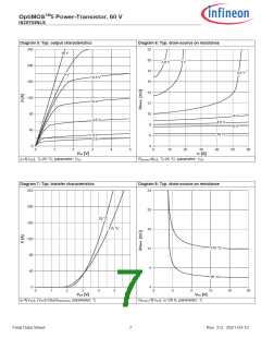
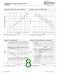
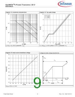
3ꢀꢀꢀꢀꢀElectricalꢀcharacteristics
atꢀTj=25ꢀ°C,ꢀunlessꢀotherwiseꢀspecified
Tableꢀ4ꢀꢀꢀꢀꢀStaticꢀcharacteristics
Values
Typ.
-
Parameter
Symbol
Unit Noteꢀ/ꢀTestꢀCondition
Min.
60
Max.
-
Drain-source breakdown voltage
Gate threshold voltage
V(BR)DSS
VGS(th)
V
V
VGS=0ꢀV,ꢀID=1ꢀmA
VDS=VGS,ꢀID=15ꢀµA
1.1
1.7
2.3
-
-
0.1
10
1
100
VDS=60ꢀV,ꢀVGS=0ꢀV,ꢀTj=25ꢀ°C
VDS=60ꢀV,ꢀVGS=0ꢀV,ꢀTj=125ꢀ°C
Zero gate voltage drain current
Gate-source leakage current
Drain-source on-state resistance
IDSS
µA
nA
IGSS
-
10
100
VGS=20ꢀV,ꢀVDS=0ꢀV
-
-
6.4
8.1
7.3
9.2
VGS=10ꢀV,ꢀID=20ꢀA
VGS=4.5ꢀV,ꢀID=10ꢀA
RDS(on)
mΩ
Gate resistance1)
Transconductance
RG
gfs
-
-
1.2
50
-
-
Ω
-
S
|VDS|≥2|ID|RDS(on)max,ꢀID=20ꢀA
Tableꢀ5ꢀꢀꢀꢀꢀDynamicꢀcharacteristics
Values
Typ.
Parameter
Symbol
Unit Noteꢀ/ꢀTestꢀCondition
Min.
Max.
Input capacitance1)
Output capacitance1)
Reverse transfer capacitance1)
Ciss
Coss
Crss
-
-
-
1100 1400 pF
VGS=0ꢀV,ꢀVDS=30ꢀV,ꢀf=1ꢀMHz
VGS=0ꢀV,ꢀVDS=30ꢀV,ꢀf=1ꢀMHz
VGS=0ꢀV,ꢀVDS=30ꢀV,ꢀf=1ꢀMHz
250
14
320
24
pF
pF
VDD=30ꢀV,ꢀVGS=4.5ꢀV,ꢀID=20ꢀA,
RG,ext=3ꢀΩ
Turn-on delay time
Rise time
td(on)
tr
td(off)
tf
-
-
-
-
6.6
1.8
13
-
-
-
-
ns
ns
ns
ns
VDD=30ꢀV,ꢀVGS=4.5ꢀV,ꢀID=20ꢀA,
RG,ext=3ꢀΩ
VDD=30ꢀV,ꢀVGS=4.5ꢀV,ꢀID=20ꢀA,
RG,ext=3ꢀΩ
Turn-off delay time
Fall time
VDD=30ꢀV,ꢀVGS=4.5ꢀV,ꢀID=20ꢀA,
RG,ext=3ꢀΩ
2.5
Tableꢀ6ꢀꢀꢀꢀꢀGateꢀchargeꢀcharacteristics2)ꢀ
Values
Typ.
3.0
Parameter
Symbol
Unit Noteꢀ/ꢀTestꢀCondition
Min.
Max.
Gate to source charge
Gate charge at threshold
Gate to drain charge
Switching charge
Qgs
-
-
-
-
-
-
-
-
-
-
nC
nC
nC
nC
nC
V
VDD=30ꢀV,ꢀID=20ꢀA,ꢀVGS=0ꢀtoꢀ4.5ꢀV
VDD=30ꢀV,ꢀID=20ꢀA,ꢀVGS=0ꢀtoꢀ4.5ꢀV
VDD=30ꢀV,ꢀID=20ꢀA,ꢀVGS=0ꢀtoꢀ4.5ꢀV
VDD=30ꢀV,ꢀID=20ꢀA,ꢀVGS=0ꢀtoꢀ4.5ꢀV
VDD=30ꢀV,ꢀID=20ꢀA,ꢀVGS=0ꢀtoꢀ4.5ꢀV
VDD=30ꢀV,ꢀID=20ꢀA,ꢀVGS=0ꢀtoꢀ4.5ꢀV
VDD=30ꢀV,ꢀID=20ꢀA,ꢀVGS=0ꢀtoꢀ10ꢀV
VDS=0.1ꢀV,ꢀVGS=0ꢀtoꢀ10ꢀV
Qg(th)
Qgd
1.7
-
3.0
-
Qsw
4.3
-
Gate charge total1)
Qg
8.7
11
-
Gate plateau voltage
Gate charge total1)
Vplateau
Qg
2.8
17
23
-
nC
nC
nC
Gate charge total, sync. FET
Output charge
Qg(sync)
Qoss
15
15
-
VDS=30ꢀV,ꢀVGS=0ꢀV
1) Defined by design. Not subject to production test.
2) See ″Gate charge waveforms″ for parameter definition
Final Data Sheet
4
Rev.ꢀ2.0,ꢀꢀ2021-03-12

 INFINEON [ Infineon ]