Quasi-Resonant PWM Controller
ICE2QS01
Electrical Characteristics
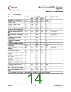
4.3.2
PWM Section
Parameter
Symbol
Limit Values
Unit
Test Condition
min.
14
typ.
23
max.
Regulation Pull-Up Resistor
PWM-OP Gain
RREG
AV
33
-
kΩ
-
3.18
0.63
18
3.3
0.7
21
Offset for Voltage Ramp
Soft-Start time
VOS
-
V
tSOFTS
38
110
ms
mV
V
Zero crossing threshold voltage VZCT1
Ringing suppression threshold VZCT2
20
50
0.7
4.2
Minimum ringing suppression
time
tZCRST1
tZCRST2
VRM
2.2
-
5.5
-
µs
VZC > VZCT2
VZC < VZCT2
Maximum ringing suppression
time
42
µs
V
Threshold to set Up/Down
Counter to one
3.9
3.2
Threshold for downward
counting
VRH
V
Threshold for upward counting VRL
2.5
48
42
V
Counter time1)
tCOUNT
ms
µs
Maximum restart time in normal tsMax
operation
33
60
VZC<VZCT1
Leading Edge Blanking
tLEB
200
330
1.0
460
ns
V
Peak current limitation in normal Vcsth
operation
0.95
1.05
Regulation voltage for entering VEB
Burst Mode
1.1
4.5
V
V
Regulation voltage for leaving
Burst Mode
VLB
Regulation voltage for burst-on VBH
Regulation voltage for burst-off VBL
3.6
3.0
80
V
V
Fixed Switching Frequency in
Burst Mode
fsB
64
96
kHz
Max. Duty Cycle in Burst Mode DmaxB
0.5
Peak Current Limitation in Burst VcsB
Mode
0.22
0.25
0.3
V
1) The parameter is not subject to production test - verified by design/characterization
Version 2.1
14
26 October 2007

 INFINEON [ Infineon ]