CCM-PFC
ICE2PCS01/G
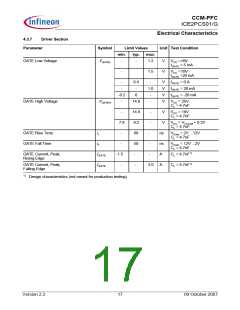
Electrical Characteristics
4
Electrical Characteristics
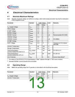
4.1
Absolute Maximum Ratings
Note: Absolute maximum ratings are defined as ratings, which when being exceeded may lead to destruction
of the integrated circuit.
Parameter
Symbol
Limit Values
Unit
Remarks
min.
max.
25
5
VCC Supply Voltage
FREQ Voltage
VCC
-0.3
-0.3
-0.3
-20
-1
V
VFREQ
VICOMP
VISENSE
IISENSE
VVSENSE
IVSENSE
VVCOMP
VGATE
V
ICOMP Voltage
ISENSE Voltage
ISENSE Current
VSENSE Voltage
VSENSE Current
VCOMP Voltage
GATE Voltage
5
V
2)
5
V
1
mA
V
Recommended R2=220Ω
-0.3
-1
5
1
mA
V
R3>400kΩ
-0.3
-0.3
5
17
V
Clamped at 15V if driven
internally.
Junction Temperature
Storage Temperature
Tj
-40
-55
-
150
150
185
°C
TS
°C
Thermal Resistance
R
thJA (DSO)
K/W
PG-DSO-8-13
Junction-Ambient for DSO-8-13
Thermal Resistance
R
thJA(DIP)
-
-
90
2
K/W
kV
PG-DIP-8-4
Junction-Ambient for DIP-8-4
ESD Protection
VESD
Human Body Model1)
1)
According to EIA/JESD22-A114-B (discharging a 100pF capacitor through a 1.5kΩ series resistor)
2)
Absolute ISENSE current should not be exceeded
4.2
Operating Range
Note: Within the operating range the IC operates as described in the functional description.
Parameter
Symbol
Limit Values
min. max.
VCCUVLO 25
-40 125
Unit
Remarks
VCC Supply Voltage
VCC
V
Junction Temperature
TJCon
°C
Version 2.2
13
09 October 2007

 INFINEON [ Infineon ]