CoolSET™-F2
ICE2A165/265/365
ICE2A180/280
Electrical Characteristics
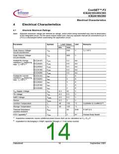
4.2
Operating Range
Note: Within the operating range the IC operates as described in the functional description.
Parameter
Symbol
Limit Values
Unit
Remarks
min.
max.
21
VCC Supply Voltage
VCC
VCCoff
-25
V
Junction Temperature of
Controller
TJCon
130
°C
limited due to thermal shut down of
controller
Junction Temperature of
TJCoolMOS
-25
150
°C
CoolMOS™
4.3
Characteristics
Note: The electrical characteristics involve the spread of values guaranteed within the specified supply voltage
and junction temperature range TJ from – 25 °C to 125 °C.Typical values represent the median values,
which are related to 25°C. If not otherwise stated, a supply voltage of VCC = 15 V is assumed.
4.3.1
Supply Section
Parameter
Symbol
Limit Values
Unit
Test Condition
min.
typ.
27
max.
Start Up Current
IVCC1
IVCC2
-
-
55
µA
VCC=VCCon -0.1V
VSoftS = 0
Supply Current with Inactiv
Gate
5.0
6.6
mA
I
FB = 0
Supply Current
with Activ Gate
ICE2A165
ICE2A265
ICE2A365
ICE2A180
ICE2A280
IVCC3
IVCC3
IVCC3
IVCC3
IVCC3
-
-
-
-
-
6.5
6.7
8.5
6.5
7.7
7.8
8
mA
mA
mA
mA
mA
VSoftS = 5V
I
FB = 0
VSoftS = 5V
I
FB = 0
9.8
7.8
9
VSoftS = 5V
I
FB = 0
VSoftS = 5V
I
FB = 0
VSoftS = 5V
I
FB = 0
VCC Turn-On Threshold
VCC Turn-Off Threshold
VCC Turn-On/Off Hysteresis
VCCon
VCCoff
VCCHY
13
-
4.5
13.5
8.5
5
14
-
5.5
V
V
V
4.3.2
Internal Voltage Reference
Parameter
Symbol
Limit Values
Unit
Test Condition
min.
typ.
max.
6.63
Trimmed Reference Voltage
VREF
6.37
6.50
V
measured at pin FB
Datasheet
15
September 2001

 INFINEON [ Infineon ]