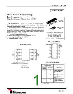
IN74HCT245A
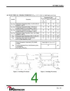
AC ELECTRICAL CHARACTERISTICS (VCC =5.0 V ± 10%, CL=50pF,Input tr=tf=6.0 ns)
Guaranteed Limit
≤85°C ≤125°C
Symbol
Parameter
Unit
25 °C
to
-55°C
tPLH, tPHL Maximum Propagation Delay, A to B or B to A
(Figures 1 and 3)
22
32
30
12
28
40
38
15
33
48
45
18
ns
ns
ns
ns
tPLZ, tPHZ Maximum Propagation Delay , Direction or
Output Enable to A or B (Figures 2 and 4)
tPZL, tPZH Maximum Propagation Delay , Direction or
Output Enable to A or B (Figures 2 and 4)
tTLH, tTHL Maximum Output Transition Time, Any Output
(Figures 1 and 3)
CIN
Maximum Input Capacitance (Pin 1 or Pin 19)
10
15
10
15
10
15
pF
pF
COUT
Maximum Three-State I/O Capacitance
(I/O in High-Impedance State)
Power Dissipation Capacitance (Per Enable
Output)
Typical @25°C,VCC=5.0 V
CPD
Used to determine the no-load dynamic power
consumption:
97
pF
PD=CPDVCC2f+ICCVCC
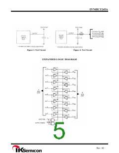
Figure 1. Switching Waveforms
Figure 2. Switching Waveforms
Rev. 00

 IKSEMICON [ IK SEMICON CO., LTD ]