IN16C1054
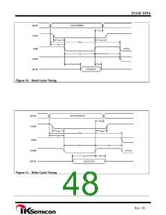
Setup time, D7~D0 valid before IOW#↑
15
2
ns
ns
ns
ns
ns
ns
tds
Hold time, A2~A0 valid after IOW#↑
twa
twcs
tdh
Hold time, CSx# valid after IOW#↑
2
Hold time, D7~D0 valid after IOW#↑
5
Delay time, taw+twr+twc
54
20
tfwc
twc
trvd
thz
Delay time, IOW#↑ to IOW# or IOR#↓
Enable time, IOR#↓ to D7~D0 valid
24
ns
Disable time, IOR# to D7~D0 released
4
ns
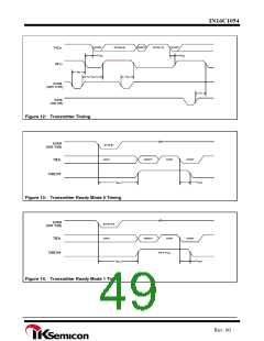
Delay time, INTx↓ to TXDx↓ at start
8
24
8
RCLK
RCLK
RCLK
RCLK
ns
tirs
Delay time, TXDx↓ at start to INTx↑
8
tsti
Delay time, IOW# high or low (WR THR) to INTx↑
Delay time, TXDx↓ at start to TXRDY#↓
16
32
8
tsi
tsxa
thr
Propagation delay time, IOW#(WR THR)↓ to INTx↓
Propagation delay time, IOR#(RD IIR)↑ to INTx↓
Propagation delay time, IOW#(WR THR) ↓ to TXRDY#↑
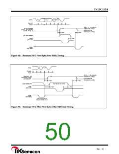
Delay time, stop bit to INTx↑ or stop bit to RXRDY# or read RBR to set interrupt
Propagation delay time, Read RBR/LSR to INTx↓/LSR interrupt↓
Propagation delay time, IOR# RCLK↓ to RXRDY#↑
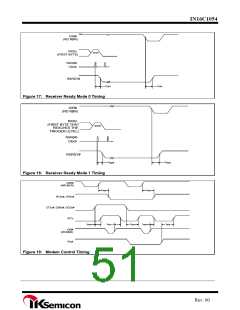
Propagation delay time, IOW#(WR MCR)↑ to RTSx#, DTRx#↑
Propagation delay time, modem input CTSx#, DSRx#, and DCDx#↓↑ to INTx↑
Propagation delay time, IOR#(RD MSR)↑ to interrupt↓
Propagation delay time, Rix#↑ to INTx#↓
12
12
10
ns
tir
ns
twxi
tsint
trint
trint
tmdo
tsim
trim
tsim
1
RCLK
ns
12
12
12
12
3
ns
ns
ns
ns
12
ns
† The internal address strobe is always in active state.
‡ In the FIFO mode, td1= xxns (min) between reads of the FIFO and the status register.
Rev. 00

 IKSEMICON [ IK SEMICON CO., LTD ]