IDTQS3VH244
2.5V/3.3V8-BITHIGHBANDWIDTHBUSSWITCH
INDUSTRIALTEMPERATURERANGE
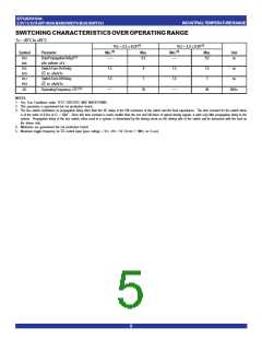
SWITCHINGCHARACTERISTICSOVEROPERATINGRANGE
TA = -40°C to +85°C
VCC = 2.5 ± 0.2V (1)
VCC = 3.3 ± 0.3V (1)
(4)
(4)
Symbol
tPLH
tPHL
tPZL
tPZH
Parameter
Max.
Min.
Max.
Unit
DataPropagationDelay(2,3)
xAx to/from xYx
SwitchTurn-OnDelay
xG to xAx/xYx
Min.
0.2
0.2
ns
1.5
8
1.5
1.5
7.5
7
ns
ns
tPLZ
SwitchTurn-OffDelay
1.5
7
tPHZ
xG to xAx/xYx
fxG
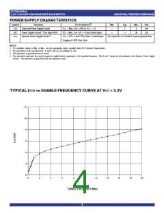
OperatingFrequency-xG(2,5)
10
20
MHz
NOTES:
1. See Test Conditions under TEST CIRCUITS AND WAVEFORMS.
2. This parameter is guaranteed but not production tested.
3. The bus switch contributes no propagation delay other than the RC delay of the ON resistance of the switch and the load capacitance. The time constant for the switch alone
is of the order of 0.2ns at CL = 50pF. Since this time constant is much smaller than the rise and fall times of typical driving signals, it adds very little propagation delay to the
system. Propagation delay of the bus switch, when used in a system, is determined by the driving circuit on the driving side of the switch and its interaction with the load on
the driven side.
4. Minimums are guaranteed but not production tested.
5. Maximum toggle frequency for xG control input (pass voltage > VCC, VIN = 5V, RLOAD ≥ 1MΩ, no CLOAD).
5

 IDT [ INTEGRATED DEVICE TECHNOLOGY ]