IDTQS3VH244
INDUSTRIALTEMPERATURERANGE
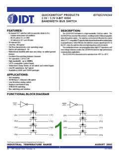
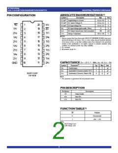
2.5V/3.3V8-BITHIGHBANDWIDTHBUSSWITCH
POWERSUPPLYCHARACTERISTICS
Symbol
ICCQ
Parameter
TestConditions(1)
Min.
—
Typ.
1
Max.
4
Unit
mA
µA
Quiescent Power Supply Current
Power Supply Current (2,3) per Input HIGH
Dynamic Power Supply Current (4)
VCC = Max., VIN = GND or VCC, f = 0
VCC = Max., VIN = 3V, f = 0 per Control Input
VCC = 3.3V, A and Y Pins Open, Control Inputs
Toggling @ 50% Duty Cycle
∆ICC
—
—
30
ICCD
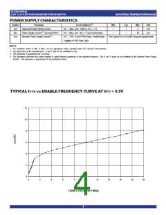
See Typical ICCD vs Enable Frequency graph below
NOTES:
1. For conditions shown as Min. or Max., use the appropriate values specified under DC Electrical Characteristics.
2. Per input driven at the specified level. A and Y pins do not contribute to ∆Icc.
3. This parameter is guaranteed but not tested.
4. This parameter represents the current required to switch internal capacitance at the specified frequency. The A and Y inputs do not contribute to the Dynamic Power Supply
Current. This parameter is guaranteed but not production tested.
CCD
CC
TYPICAL I
vs ENABLE FREQUENCY CURVE AT V = 3.3V
12
10
8
6
4
2
0
0
2
4
6
8
10
12
14
16
18
20
ENABLE FREQUENCY (MHz)
4

 IDT [ INTEGRATED DEVICE TECHNOLOGY ]