ICM7115
LOW COST SINGLE CHIP TELEPHONE IC
WITH VOLUME CONTROL
present, the typical AC impedance is 1000Ω.
DTMF Tones
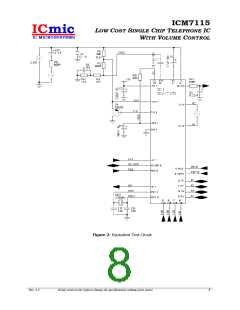
Refer to Figure 2 for the equivalent test circuit.
RZAC=100KΩ typically sets the AC impedance
to 600Ω. Please note that the overall system
AC impedance also depends on the whole
system circuit.
The DTMF tone generator creates 12 tones in
compliance with CCITT Recommendation.
There are two group of frequencies of DTMF
tones. The low group depends on the key’s
row, while the high group depends on the
key’s column as illustrated in the following
table:
DTMF Signal Level
DTMF signal level can be selected by setting
MFL0 pin as follow:
C1B
C2B
C3B
Low
Freq
MFL0
DTMF level
R1
R2
R3
R4
1
4
7
*
2
5
8
0
3
6
9
697 Hz
770 Hz
852 Hz
941 Hz
0
1
Low, typical -8/-10dB
High, typical -6/-8dB
#
High Freq 1209 Hz 1336 Hz 1477 Hz
DIALING FUNCTIONS
Keypad arrangement is as shown in the typical
application circuit in Appendix A. Dialing
modes are selectable using the pull-up/pull-
down resistors connected to the row inputs.
Last Number Redial (LNR)
The last Number Redial (LNR) is a facility of
ICM7115 to allow resignalling of the last
manually dialled number without keying in all
digits again. The LNR is repeatable after each
off-hook.
As soon as the phone goes off-hook (i.e when
HS_DPB pin goes HIGH), voltage levels on
keypad row inputs (R1 thru R4) are first
scanned to determine the operating mode as
follow:
A manually entered number is stored in
internal 32-digit RAM. VDD shall not fall below
1.0V during on-hook state to properly retain
the data in the memory.
Pin
R1
Function
Dialing Mode
Level – Mode
0 – MF mode
1 – Pulse mode
0 – 10 PPS
1 – 20 PPS
0 – 40/60
1 – 33/67
0 – 82ms/82ms
1 – 82ms/160ms
R2
R3
R4
Pulse Period
Flash
ICM7115 asserts line break (pulls down
HS_DPB pin) when Flash key is depressed. The
flash duration depends on the input levels of
FOPT0 pin as follow:
Make/Break
Ratio
DTMF option
FOPT0 Flash Duration
0
1
300 ms
600 ms
Valid Keys
ICM7115 has a total of 16 valid keys. It scans
the keys by asserting known state on pins R1,
R2, R3, and R4 in sequence, and check which
column (pins C1B, C2B, C3B, C4B) is shorted
to which row. The following specify the
combinations:
Vol_Up
When Vol_Up key is depressed ICM7115
increases the receive gain by 13.5dB in three
steps (from default level).
Vol_Down
C1B
1
4
C2B
2
5
C3B
3
6
C4B
Vol_up
Vol_Down
Flash
When Vol_Down key is depressed ICM7115
decreases the receive gain by -10.5dB in four
steps (from default level).
R1
R2
R3
R4
7
8
9
*
0
#
LNR
Rev. 2.5
ICmic reserves the right to change the specifications without prior notice
5

 ICMIC [ IC MICROSYSTEMS ]