For VE Items (in which Aluminum Is Used Above and Below the Ground Board and the
Eyelets Protrude Beyond the Cover)
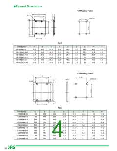
The height of the cover will be a value 0.1 mm less than one half of the overall thickness.
For Directional Card Couplers (HD-0900M (10 dB) and HD-0900M (20 dB),etc.)
The height of the cover will be a value 0.35 mm less than one half of the overall thickness.
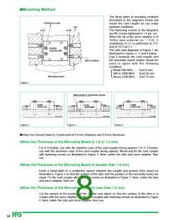
(When Spacing H of the Micro Stripline Board and the Tabs is 0 ≤ H ≤ 0.3 mm)
Fix the card coupler with fastening screws as illustrated in Figure 2.
Next, solder the tabs and micro stripline, then use.
(When Spacing H of the Micro Stripline Board and the Tabs is H < 0)
Insert a metal plate or a conductive spacer between the coupler and ground, then mount as
illustrated in Figure 3 so that the surface of the tabs and the position of the microstrip board are
equal. Fix the card coupler with fastening screws as illustrated in Figure 3. Next, solder the tabs
and micro stripline, then use.
(When Spacing H of the Micro Stripline Board and the Tabs is H > 0.3 mm)
Cut the ground at the position of the coupler and attach so that the surface of the tabs is in
contact with the micro stripline. Fix the card coupler with fastening screws as illustrated in Figure
4. Next, solder the tabs and micro stripline, then use.
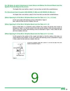
At the time of soldering, solder with a space of 1 mm from the edge of the micro
stripline as illustrated in Figure 5.
Soldering portion
Micro stripline board
Figure 5.
35

 HRS [ HRS ]