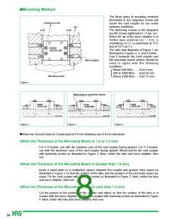
ꢀMounting Method
The three types of mounting methods
illustrated in the diagrams below will
mount the card coupler for use under
optimum conditions.
Fastening screw
Tab
The fastening screws in the diagrams
are M2 screws tightened to 1.5 kg • cm.
When the tip of the micro stripline is of
Teflon type material ( r = 2.6), C
chamfering of C1 is performed at t1.6,
and of C0.5 at t1.2.
The side view diagrams of Figure 1 are
illustrated in Figures 2, 3, and 4 below.
Gap S between the card coupler and
the microstrip board surface should be
used to agree with the following
conditions.
Micro stripline
........
Below 500 MHz
500 to 2300 MHz
Above 2300 MHz
S≤0.5 mm
S≤0.25 mm
S≤0.15 mm
......
......
(
Microstrip board
Figure 1.
Metal plate or conductive spacer
Figure 2.
Figure 3.
Figure 4.
ꢀWhen the Ground Board is Constructed of 0.4 mm Stainless and 0.8 mm Aluminum
(When the Thickness of the Microstrip Board is 1.6 or 1.2 mm)
For t1.6 boards, use with the stainless case of the card coupler facing upward. For t1.2 boards,
use with the aluminum case of the card coupler facing upward. Mount and fix the card coupler
with fastening screws as illustrated in Figure 2. Next, solder the tabs and micro stripline, then
use.
(When the Thickness of the Microstrip Board is Greater than 1.6 mm)
Insert a metal plate or a conductive spacer between the coupler and ground, then mount as
illustrated in Figure 3 so that the surface of the tabs and the position of the microstrip board are
equal. Fix the card coupler with fastening screws as illustrated in Figure 3. Next, solder the tabs
and micro stripline, then use.
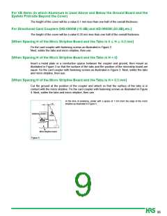
(When the Thickness of the Microstrip Board is Less than 1.2 mm)
Cut the ground at the position of the coupler and attach so that the surface of the tabs is in
contact with the micro stripline. Fix the card coupler with fastening screws as illustrated in Figure
4. Next, solder the tabs and micro stripline, then use.
34

 HRS [ HRS ]