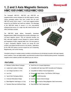
HMC1051/HMC1052/HMC1053
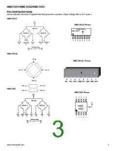
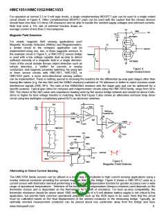
PIN CONFIGURATIONS
(Arrow indicates direction of applied field that generates a positive output voltage after a SET pulse.)
HMC1051Z
Vcc
(3)
HMC1051Z Pinout
HMC1051
HONEYWELL
HMC1051Z
BRIDGE A
BRIDGE B
1
2 3 4 5 6 7 8
Vo+(A)
(2)
Vo-(A)
(8)
GND1(B) GND2(B)
GND Plane
(4)
(1)
(5)
Set/Reset Strap
S/R+
(6)
S/R-
(7)
HMC1051ZL
HMC1051ZL Pinout
8
7
6
5
4
3
2
1
VB VO+ OFF+ GND VO- S/R- S/R+ OFF-
HMC1052
HMC1052 Pinout
Vcc
(5)
10
9
8
7
6
HMC1052
B
BRIDGE A
BRIDGE B
HMC
1052
A
OUT- GND2 GND1 OUT+ OUT-
(10) (9) (3) (4) (7)
GND
(1)
OUT+
(2)
1
2
3
4
5
Set/Reset Strap
S/R+
(6)
S/R-
(8)
www.honeywell.com
3

 HONEYWELL [ Honeywell ]