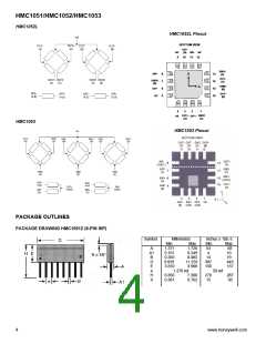
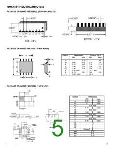
HMC1051/HMC1052/HMC1053
APPLICATION NOTES
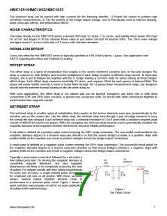
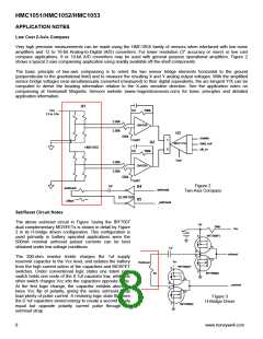
Low Cost 2-Axis Compass
Very high precision measurements can be made using the HMC105X family of sensors when interfaced with low noise
amplifiers and 12 to 16-bit Analog-to-Digital (A/D) converters. For lower resolution (3° accuracy or more) or low cost
compass applications, 8 or 10-bit A/D converters may be used with general purpose operational amplifiers. Figure 2
shows a typical 2-axis compassing application using readily available off-the-shelf components.
The basic principle of two-axis compassing is to orient the two sensor bridge elements horizontal to the ground
(perpendicular to the gravitational field) and to measure the resulting X and Y analog output voltages. With the amplified
sensor bridge voltages near-simultaneously converted (measured) to their digital equivalents, the arc-tangent Y/X can be
computed to derive the heading information relative to the X-axis sensitive direction. See the application notes on
compassing at Honeywell Magnetic Sensors website (www.magneticsensors.com) for basic principles and detailed
application information.
U1
Vcc
1nf
500k
2.5 to 3.6v
5.00k
5.00k
LMV358
U3
500k
enable
data_out
clk_in
Vref/2
1nf
1
0
U2
MAX1118
HMC1052
500k
Vref
5.00k
5.00k
LMV358
500k
Vref/2
Figure 2
Two-Axis Compass
.1uf
U4
set/reset
offset
set/reset
(2) IRF7509
U5
_set/reset
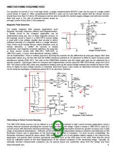
Set/Reset Circuit Notes
The above set/reset circuit in Figure 1using the IRF7507
dual complementary MOSFETs is shown in detail by Figure
2 in its H-bridge driven configuration. This configuration is
used primarily in battery operated applications were the
500mA nominal set/reset pulsed currents can be best
obtained under low voltage conditions.
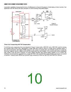
Vsr
200Ω
Vcc
1µf
+
-
IRF7509(P)
G
S
.1µf
D
D
set/reset
The 200-ohm resistor trickle charges the 1uf supply
reservoir capacitor to the Vcc level, and isolates the battery
from the high current action of the capacitors and MOSFET
switches. Under conventional logic states one totem pole
switch holds one node of the 0.1uf capacitor low, while the
other switch charges Vcc into the capacitors opposite node.
At the first logic change, the capacitor exhibits almost a
twice Vcc flip of polarity, giving the series set/reset strap
load plenty of pulse current. A restoring logic state flip uses
the 0.1uf capacitors stored energy to create a second nearly
equal but opposite polarity current pulse through the
set/reset strap.
G
Vsr
Rset/reset
IRF7509(P)
G
S
S
IRF7509(N)
4Ω
D
D
_set/reset
G
Figure 3
H-Bridge Driver
S
IRF7509(N)
8
www.honeywell.com

 HONEYWELL [ Honeywell ]