HT46R23/HT46C23
0
0
0
0
0
0
0
4
8
H
H
H
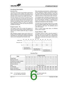
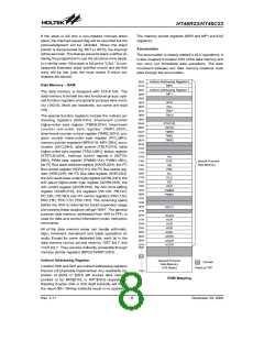
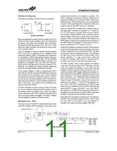
Certain locations in the program memory are reserved
for special usage:
D
e
v
i
c
e
I
n
i
t
i
a
l
i
z
a
t
i
o
n
P
r
o
g
r
a
m
E
x
t
e
r
n
a
l
I
n
t
e
r
r
u
p
t
S
u
b
r
o
u
t
i
n
e
·
Location 000H
This area is reserved for program initialization. After
chip reset, the program always begins execution at lo-
cation 000H.
T
i
m
e
r
/
E
v
e
n
t
C
o
u
n
t
e
r
I
n
t
e
r
r
u
p
t
S
u
b
r
o
u
t
i
n
e
0
0
C
H
A
/
D
C
o
n
v
e
r
t
e
r
I
n
t
e
r
r
u
p
t
S
u
b
r
o
u
t
i
n
e
·
Location 004H
P
r
o
g
r
a
m
0
1
0
H
This area is reserved for the external interrupt service
program. If the INT input pin is activated, the interrupt
is enabled and the stack is not full, the program begins
execution at location 004H.
2
M
e
m
o
r
y
I
C
B
u
s
I
n
t
e
r
r
u
p
t
S
u
b
r
o
u
t
i
n
e
n
0
0
H
·
·
·
L
o
o
k
-
u
p
T
a
b
l
e
(
2
5
6
w
o
r
d
s
)
Location 008H
n
F
F
H
This area is reserved for the timer/event counter inter-
rupt service program. If a timer interrupt results from a
timer/event counter overflow, and if the interrupt is en-
abled and the stack is not full, the program begins exe-
cution at location 008H.
F
0
0
H
L
o
o
k
-
u
p
T
a
b
l
e
(
2
5
6
w
o
r
d
s
)
F
F
F
H
1
5
b
i
t
s
N
o
t
e
:
n
r
a
n
g
e
s
f
r
o
m
0
t
o
F
Location 00CH
This area is reserved for the A/D converter interrupt
service program. If an A/D converter interrupt results
from an end of A/D conversion, and if the interrupt is
enabled and the stack is not full, the program begins
execution at location 00CH.
Program Memory
changed by the table read instruction used in the ISR.
Errors can occur. In other words, using the table read
instruction in the main routine and the ISR simulta-
neously should be avoided. However, if the table read
instruction has to be applied in both the main routine
and the ISR, the interrupt is supposed to be disabled
prior to the table read instruction. It will not be enabled
until the TBLH has been backed up. All table related
instructions require two cycles to complete the opera-
tion. These areas may function as normal program
memory depending upon the requirements.
Location 010H
This area is reserved for the I2C Bus interrupt service
program. If the I2C Bus interrupt resulting from a slave
address is match or completed one byte of data trans-
fer, and if the interrupt is enable and the stack is not
full, the program begins execution at location 010H.
·
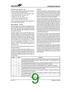
Table location
Any location in the PROM space can be used as
look-up tables. The instructions ²TABRDC [m]² (the
current page, 1 page=256 words) and ²TABRDL [m]²
(the last page) transfer the contents of the lower-order
byte to the specified data memory, and the
higher-order byte to TBLH (08H). Only the destination
of the lower-order byte in the table is well-defined, the
other bits of the table word are transferred to the lower
portion of TBLH, and the remaining 1 bit is read as ²0².
The Table Higher-order byte register (TBLH) is read
only. The table pointer (TBLP) is a read/write register
(07H), which indicates the table location. Before ac-
cessing the table, the location must be placed in
TBLP. The TBLH is read only and cannot be restored.
If the main routine and the ISR (Interrupt Service Rou-
tine) both employ the table read instruction, the con-
tents of the TBLH in the main routine are likely to be
Stack Register - STACK
This is a special part of the memory which is used to
save the contents of the program counter (PC) only. The
stack is organized into 8 levels and is neither part of the
data nor part of the program space, and is neither read-
able nor writeable. The activated level is indexed by the
stack pointer (SP) and is neither readable nor writeable.
At a subroutine call or interrupt acknowledgment, the
contents of the program counter are pushed onto the
stack. At the end of a subroutine or an interrupt routine,
signaled by a return instruction (RET or RETI), the pro-
gram counter is restored to its previous value from the
stack. After a chip reset, the SP will point to the top of the
stack.
Table Location
Instruction
*11
P11
1
*10
P10
1
*9
P9
1
*8
P8
1
*7
*6
*5
*4
*3
*2
*1
*0
TABRDC [m]
TABRDL [m]
@7
@7
@6
@6
@5
@5
@4
@4
@3
@3
@2
@2
@1
@1
@0
@0
Table Location
P11~P8: Current program counter bits
Note: *11~*0: Table location bits
@7~@0: Table pointer bits
Rev. 2.11
7
December 29, 2008
图片预览")
 HOLTEK [ HOLTEK SEMICONDUCTOR INC ]