HT46R23/HT46C23
Power Down Operation - HALT
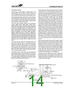
set² that resets only the program counter and stack
pointer, leaving the other circuits in their original state.
Some registers remain unchanged during other reset
conditions. Most registers are reset to the ²initial condi-
tion² when the reset conditions are met. By examining
the PDF and TO flags, the program can distinguish be-
tween different ²chip resets².
The HALT mode is initialized by the ²HALT² instruction
and results in the following...
·
·
·
The system oscillator will be turned off but the WDT os-
cillator keeps running (if the WDT oscillator is selected).
The contents of the on chip RAM and registers remain
unchanged.
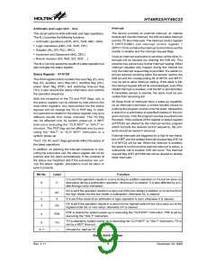
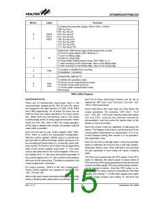
TO PDF
RESET Conditions
RES reset during power-up
RES reset during normal operation
RES wake-up HALT
WDT will be cleared and recounted again (if the WDT
clock is from the WDT oscillator).
0
u
0
1
1
0
u
1
u
1
·
·
All of the I/O ports maintain their original status.
The PDF flag is set and the TO flag is cleared.
The system can leave the HALT mode by means of an ex-
ternal reset, an interrupt, an external falling edge signal on
port A or a WDT overflow. An external reset causes a de-
vice initialization and the WDT overflow performs a ²warm
reset². After the TO and PDF flags are examined, the rea-
son for chip reset can be determined. The PDF flag is
cleared by system power-up or executing the ²CLR WDT²
instruction and is set when executing the ²HALT² instruc-
tion. The TO flag is set if the WDT time-out occurs, and
causes a wake-up that only resets the program counter
and stack pointer; the others keep their original status.
WDT time-out during normal operation
WDT wake-up HALT
Note: ²u² means ²unchanged²
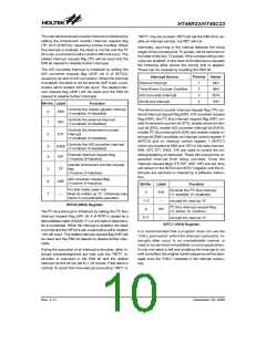
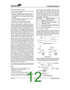
To guarantee that the system oscillator is started and
stabilized, the SST (System Start-up Timer) provides an
extra-delay of 1024 system clock pulses when the sys-
tem reset (power-up, WDT time-out or RES reset) or the
system awakes from the HALT state.
V
D
D
The port A wake-up and interrupt methods can be con-
sidered as a continuation of normal execution. Each bit
in port A can be independently selected to wake up the
device by the options. Awakening from an I/O port stim-
ulus, the program will resume execution of the next in-
struction. If it is awakening from an interrupt, two
sequences may happen. If the related interrupt is dis-
abled or the interrupt is enabled but the stack is full, the
program will resume execution at the next instruction. If
the interrupt is enabled and the stack is not full, the regu-
lar interrupt response takes place. If an interrupt request
flag is set to ²1² before entering the HALT mode, the
wake-up function of the related interrupt will be disabled.
Once a wake-up event occurs, it takes 1024 tSYS (sys-
tem clock period) to resume normal operation. In other
words, a dummy period will be inserted after wake-up. If
the wake-up results from an interrupt acknowledgment,
the actual interrupt subroutine execution will be delayed
by one or more cycles. If the wake-up results in the next
instruction execution, this will be executed immediately
after the dummy period is finished.
R
E
S
t
S S T
S
S
T
T
i
m
e
-
o
u
t
C
h
i
p
R
e
s
e
t
Reset Timing Chart
V
D
D
V
D
D
m
0 . 0 1 F
1
0
0
k
1
0
0
k
R
E
S
R
E
S
m
0 . 1 F
1
0
k
B
a
s
i
c
H
i
-
n
o
i
s
e
R
e
s
e
t
R
e
s
e
t
m
0 . 1 F
C
i
r
c
u
i
t
C
i
r
c
u
i
t
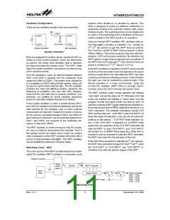
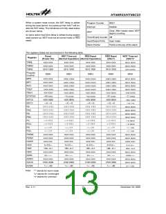
Reset Circuit
Note: Most applications can use the Basic Reset Circuit
as shown, however for applications with extensive noise,
it is recommended to use the Hi-noise Reset Circuit.
H
A
L
T
To minimize power consumption, all the I/O pins should
be carefully managed before entering the HALT status.
W
a
r
m
R
e
s
e
t
W
D
T
Reset
R
E
S
There are three ways in which a reset can occur:
C
o
l
d
R
e
s
e
t
·
·
·
RES reset during normal operation
RES reset during HALT
S
S
T
1
0
-
b
i
t
R
i
p
p
l
e
O
S
C
1
C
o
u
n
t
e
r
WDT time-out reset during normal operation
S
y
s
t
e
m
R
e
s
e
t
The WDT time-out during HALT is different from other
chip reset conditions, since it can perform a ²warm re -
Reset Configuration
Rev. 2.11
12
December 29, 2008
图片预览")
 HOLTEK [ HOLTEK SEMICONDUCTOR INC ]