HT46R064B/065B/066B
Wake-up
Note: 1. tRSTD (reset delay time), tSYS (system clock)
2. tRSTD is power-on delay, typical time=100ms
3. tSST1= 2 tSYS
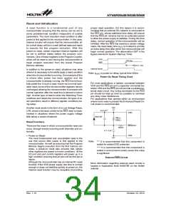
After the system enters the Idle/Sleep Mode, it can be
woken up from one of various sources listed as follows:
4. tSST2= 128 tSYS
·
·
·
·
An external reset
Wake-up Delay Time
An external falling edge on PA0 to PA7
A system interrupt
Watchdog Timer
A WDT overflow
The Watchdog Timer, also known as the WDT, is pro-
vided to inhibit program malfunctions caused by the pro-
gram jumping to unknown locations due to certain
uncontrollable external events such as electrical noise.
If the system is woken up by an external reset, the de-
vice will experience a full system reset, however, if the
device is woken up by a WDT overflow, a Watchdog
Timer reset will be initiated. Although both of these
wake-up methods will initiate a reset operation, the ac-
tual source of the wake-up can be determined by exam-
ining the TO and PDF flags. The PDF flag is cleared by a
system power-up or executing the clear Watchdog
Timer instructions and is set when executing the ²HALT²
instruction. The TO flag is set if a WDT time-out occurs,
and causes a wake-up that only resets the Program
Counter and Stack Pointer, the other flags remain in
their original status.
Watchdog Timer Operation
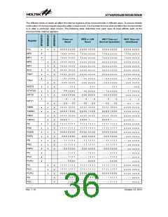
It operates by providing a device reset when the Watch-
dog Timer counter overflows. Note that if the Watchdog
Timer function is not enabled, then any instructions re-
lated to the Watchdog Timer will result in no operation.
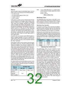
Setting up the various Watchdog Timer options are con-
trolled via the configuration options and two internal reg-
isters WDTS and CTRL1. Enabling the Watchdog Timer
can be controlled by both a configuration option and the
WDTEN bits in the CTRL1 internal register in the Data
Memory.
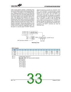
Pins PA0 to PA7 can be setup via the PAWUK register to
permit a negative transition on the pin to wake-up the
system. When a PA0 to PA7 pin wake-up occurs, the pro-
gram will resume execution at the instruction following
the ²HALT² instruction.
Configuration
Option
CTRL1
WDT
Register
Function
Disable
Disable
Enable
Disable
Enable
x
OFF
ON
If the system is woken up by an interrupt, then two possi-
ble situations may occur. The first is where the related
interrupt is disabled or the interrupt is enabled but the
stack is full, in which case the program will resume exe-
cution at the instruction following the ²HALT² instruction.
In this situation, the interrupt which woke-up the device
will not be immediately serviced, but will rather be ser-
viced later when the related interrupt is finally enabled or
when a stack level becomes free. The other situation is
where the related interrupt is enabled and the stack is
not full, in which case the regular interrupt response
takes place. If an interrupt request flag is set to ²1² be-
fore entering the Idle/Sleep Mode, then any future inter-
rupt requests will not generate a wake-up function of the
related interrupt will be ignored.
ON
Watchdog Timer On/Off Control
The Watchdog Timer will be disabled if bits
WDTEN3~WDTEN0 in the CTRL1 register are written
with the binary value 1010B and WDT configuration op-
tion is disable. This will be the condition when the device
is powered up. Although any other data written to
WDTEN3~WDTEN0 will ensure that the Watchdog
Timer is enabled, for maximum protection it is recom-
mended that the value 0101B is written to these bits.
The Watchdog Timer clock can emanate from three dif-
ferent sources, selected by configuration option. These
are LXT, fSYS/4, or LIRC. It is important to note that when
the system enters the Idle/Sleep Mode the instruction
clock is stopped, therefore if the configuration options
have selected fSYS/4 as the Watchdog Timer clock
source, the Watchdog Timer will cease to function. For
systems that operate in noisy environments, using the
LIRC or the LXT as the clock source is therefore the rec-
ommended choice. The division ratio of the prescaler is
determined by bits 0, 1 and 2 of the WDTS register,
known as WS0, WS1 and WS2. If the Watchdog Timer in-
ternal clock source is selected and with the WS0, WS1
and WS2 bits of the WDTS register all set high, the
prescaler division ratio will be 1:128, which will give a
maximum time-out period.
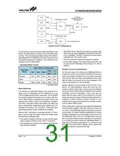
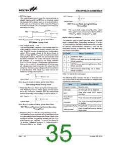
No matter what the source of the wake-up event is, once
a wake-up event occurs, there will be a time delay be-
fore normal program execution resumes. Consult the ta-
ble for the related time.
Oscillator Type
Wake-up
Source
ERC, IRC
Crystal
External RES
PA Port
tRSDT + tSST2
tRSDT + tSST2
tSST1
tSST2
Interrupt
WDT Overflow
Rev. 1.10
32
October 23, 2012

 HOLTEK [ HOLTEK SEMICONDUCTOR INC ]