HT46R064B/065B/066B
Ta=25°C
Test Conditions
Symbol
Parameter
Min.
Typ.
Max.
Unit
VDD
¾
Conditions
tINT
Interrupt Pulse Width
1
¾
¾
¾
¾
1
¾
2
ms
ms
ms
tLVR
Low Voltage Width to Reset
0.25
¾
¾
RESTD Reset Delay Time
100
¾
¾
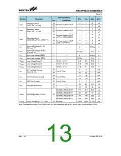
Note: 1. tSYS=1/fSYS
2. *For fERC, as the resistor tolerance will influence the frequency a precision resistor is recommended.
3. To maintain the accuracy of the internal HIRC oscillator frequency, a 0.1mF decoupling capacitor should
be connected between VDD and VSS and located as close to the device as possible.
ADC Characteristics
Ta=25°C
Test Conditions
Conditions
Symbol
DNL
Parameter
Min.
-2
Typ.
¾
Max.
Unit
LSB
LSB
VDD
3V
5V
3V
5V
3V
5V
tAD=0.5ms
A/C Differential Non-Linearity
ADC Integral Non-Linearity
2
4
t
AD=0.5ms
INL
-4
¾
0.5
1.0
0.75
1.5
mA
mA
¾
¾
Additional Power Consumption
if A/D Converter is Used
IADC
¾
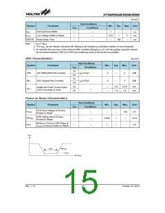
Power-on Reset Characteristics
Test Conditions
Conditions
Symbol
Parameter
Min.
Typ.
Max.
Unit
VDD
VDD Start Voltage to Ensure
Power-on Reset
VPOR
RRVDD
tPOR
100
¾
mV
V/ms
ms
¾
¾
¾
¾
¾
0.035
1
¾
¾
¾
VDD raising rate to Ensure
Power-on Reset
¾
¾
Minimum Time for VDD Stays at
¾
V
POR to Ensure Power-on Reset
V
D
D
t
P
O
R
R
V
R
D
D
V
P
O
R
T
i
m
Rev. 1.10
15
October 23, 2012

 HOLTEK [ HOLTEK SEMICONDUCTOR INC ]