HT46F46E/HT46F47E/HT46F48E/HT46F49E
Oscillator
Various oscillator options offer the user a wide range of
functions according to their various application require-
ments. Two types of system clocks can be selected
while various clock source options for the Watchdog
Timer are provided for maximum flexibility. All oscillator
options are selected through the configuration options.
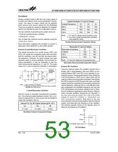
Crystal Oscillator C1 and C2 Values
Crystal Frequency
8MHz
C1
C2
CL
TBD
TBD
TBD
TBD
TBD
TBD
TBD
TBD
TBD
4MHz
The two methods of generating the system clock are:
1MHz
·
External crystal/resonator oscillator
Note: 1. C1 and C2 values are for guidance only.
2. CL is the crystal manufacturer specified
load capacitor value.
·
External RC oscillator
One of these two methods must be selected using the
configuration options.
Crystal Recommended Capacitor Values
More information regarding the oscillator is located in
Application Note HA0075E on the Holtek website.
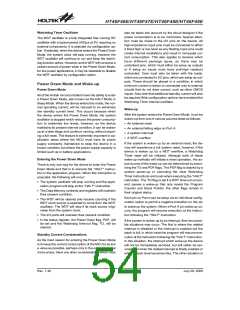
Resonator C1 and C2 Values
Resonator Frequency
3.58MHz
C1
C2
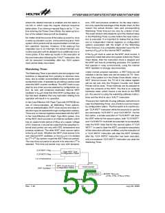
External Crystal/Resonator Oscillator
TBD
TBD
TBD
TBD
TBD
TBD
The simple connection of a crystal across OSC1 and
OSC2 will create the necessary phase shift and feed-
back for oscillation, and will normally not require exter-
nal capacitors. However, for some crystals and most
resonator types, to ensure oscillation and accurate fre-
quency generation, it may be necessary to add two
small value external capacitors, C1 and C2. The exact
values of C1 and C2 should be selected in consultation
1MHz
455kHz
Note: C1 and C2 values are for guidance only.
Resonator Recommended Capacitor Values
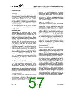
External RC Oscillator
Using the external system RC oscillator requires that a
resistor, with a value between 15kW and 750KW, is con-
nected between OSC1 and VDD, and a capacitor is con-
nected to ground. The generated system clock divided by
4 will be provided on OSC2 as an output which can be
used for external synchronization purposes. Note that as
the OSC2 output is an NMOS open-drain type, a pull high
resistor should be connected if it to be used to monitor the
internal frequency. Although this is a cost effective oscil-
lator configuration, the oscillation frequency can vary with
VDD, temperature and process variations and is there-
fore not suitable for applications where timing is critical or
where accurate oscillator frequencies are required.For
the value of the external resistor ROSC refer to the Holtek
website for typical RC Oscillator vs. Temperature and
VDD characteristics graphics. Note that it is the only
microcontroller internal circuitry together with the external
resistor, that determine the frequency of the oscillator.
The external capacitor shown on the diagram does not
influence the frequency of oscillation.
I
O
C
n
t
e
r
n
C
1
O
S
C
1
s
c
i
l
i
r
c
u
C
a
R
p
R
f
C
b
T
o
i
n
c
i
r
c
u
O
S
C
2
C
2
N
o
t
e
:
1
.
R
p
i
s
n
o
r
m
a
l
l
y
2
.
A
l
t
h
o
u
g
h
n
o
t
s
h
o
w
n
c
a
p
a
c
i
t
a
n
c
e
o
f
a
r
o
Crystal/Resonator Oscillator
with the crystal or resonator manufacturer¢s specifica-
tion. The external parallel feedback resistor, Rp, is nor-
mally not required but in some cases may be needed to
assist with oscillation start up.
Internal Ca, Cb, Rf Typical Values @ 5V, 25° C
Ca
Cb
Rf
11~13pF
13~15pF
470kW
V
D
D
Oscillator Internal Component Values
R
O
S
C
O
S
C
1
4
7
0
p
F
f
S
Y
/
S
4
N
M
O
S
O
p
O
e
S
n
C
D
2
r
a
RC Oscillator
Rev. 1.40
53
July 28, 2009

 HOLTEK [ HOLTEK SEMICONDUCTOR INC ]