HT46F46E/HT46F47E/HT46F48E/HT46F49E
W
D
T
T
i
m
e
-
o
u
t
·
RES Pin Reset
t
S
S
T
This type of reset occurs when the microcontroller is
already running and the RES pin is forcefully pulled
low by external hardware such as an external switch.
In this case as in the case of other reset, the Program
Counter will reset to zero and program execution initi-
ated from this point.
S
S
T
T
i
m
e
-
o
u
t
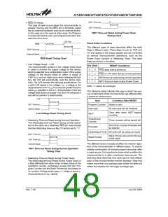
WDT Time-out Reset during Power Down
Timing Chart
0
.
D
9
D
V
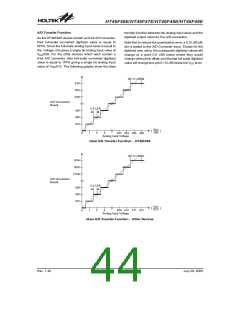
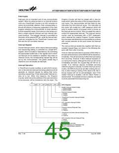
Reset Initial Conditions
0
.
D
4
D
V
R
E
S
t
R
S
T
D
The different types of reset described affect the reset
flags in different ways. These flags, known as PDF and
TO are located in the status register and are controlled
by various microcontroller operations, such as the
Power Down function or Watchdog Timer. The reset
flags are shown in the table:
S
S
T
T
i
m
e
-
o
u
t
I
n
t
e
r
n
a
l
R
e
s
e
t
RES Reset Timing Chart
·
Low Voltage Reset - LVR
TO PDF
RESET Conditions
The microcontroller contains a low voltage reset circuit
in order to monitor the supply voltage of the device,
which is selected via a configuration option. If the supply
voltage of the device drops to within a range of
0.9V~VLVR such as might occur when changing the bat-
tery, the LVR will automatically reset the device inter-
nally. The LVR includes the following specifications: For
a valid LVR signal, a low voltage, i.e., a voltage in the
range between 0.9V~VLVR must exist for greater than the
value tLVR specified in the A.C. characteristics. If the low
voltage state does not exceed 1ms, the LVR will ignore it
and will not perform a reset function.
0
u
1
1
0
u
u
1
RES reset during power-on
RES or LVR reset during normal operation
WDT time-out reset during normal operation
WDT time-out reset during Power Down
Note: ²u² stands for unchanged
The following table indicates the way in which the vari-
ous components of the microcontroller are affected after
a power-on reset occurs.
L
V
R
Item
Condition After RESET
t
R
S
T
D
S
S
T
T
i
m
e
-
o
u
t
Program Counter Reset to zero
Interrupts
WDT
All interrupts will be disabled
I
n
t
e
r
n
a
l
R
e
s
e
t
Clear after reset, WDT begins
counting
Low Voltage Reset Timing Chart
Timer/Event
Counter
·
Timer Counter will be turned off
Watchdog Time-out Reset during Normal Operation
The Watchdog time-out Reset during normal opera-
tion is the same as a hardware RES pin reset except
that the Watchdog time-out flag TO will be set to ²1².
The Timer Counter Prescaler will
be cleared
Prescaler
Input/Output Ports I/O ports will be setup as inputs
W
D
T
T
T
i
i
m
m
e
-
o
o
u
u
t
t
Stack Pointer will point to the top
t
R
S
T
D
Stack Pointer
of the stack
S
S
T
e
-
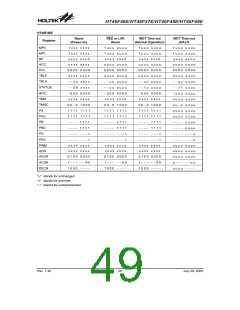
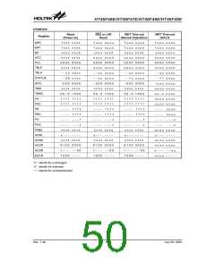
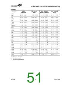
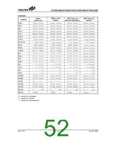
The different kinds of resets all affect the internal regis-
ters of the microcontroller in different ways. To ensure
reliable continuation of normal program execution after
a reset occurs, it is important to know what condition the
microcontroller is in after a particular reset occurs. The
following table describes how each type of reset affects
each of the microcontroller internal registers. Note that
where more than one package type exists the table will
reflect the situation for the larger package type.
I
n
t
e
r
n
a
l
R
e
s
e
t
WDT Time-out Reset during Normal Operation
Timing Chart
·
Watchdog Time-out Reset during Power Down
The Watchdog time-out Reset during Power Down is
a little different from other kinds of reset. Most of the
conditions remain unchanged except that the Pro-
gram Counter and the Stack Pointer will be cleared to
²0² and the TO flag will be set to ²1². Refer to the A.C.
Characteristics for tSST details.
Rev. 1.40
48
July 28, 2009

 HOLTEK [ HOLTEK SEMICONDUCTOR INC ]